Protective sleeve of electronic product and electronic equipment
A technology of electronic products and electronic equipment, which is applied in the field of electronic equipment, and can solve problems such as liquid blocking holes, dirty dust-proof nets, and internal device damage
- Summary
- Abstract
- Description
- Claims
- Application Information
AI Technical Summary
Problems solved by technology
Method used
Image
Examples
Embodiment 1
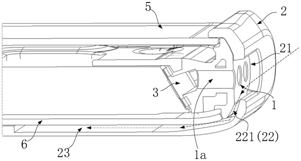
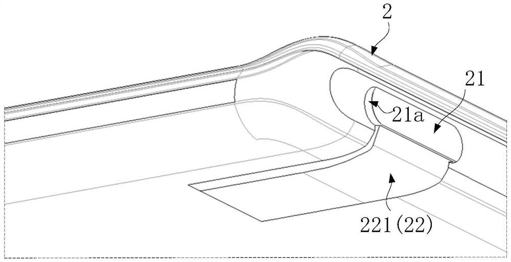
[0033] please check figure 2 , 3 , figure 2 It is a cross-sectional view of the mobile phone with the protective cover 2 in the first through hole position in Example 1 of the present application; image 3 for figure 2 Schematic diagram of part of the structure of the middle protective cover 2.
[0034] The mobile phone is provided with a first through hole 1a connecting external and internal electronic devices, figure 2 The electronic device shown in is the mobile phone sound cavity speaker 3, and the sound it sends is transmitted to the outside through the sound hole, and the sound hole is the first through hole 1a shown in this embodiment, and the first through hole 1a can be opened in on the casing of electronic products, figure 2 The first through hole 1a is set at the end of the middle frame 1 of the mobile phone, and shows a plurality of sound holes, which penetrate the middle frame 1 to communicate with the outside. The top and bottom of the middle frame 1 ar...
Embodiment 2
[0041] Please refer to Figure 4 , Figure 4 It is a partial structural schematic diagram of the protective sheath 2 in Example 2 of the present application.
[0042] Embodiment 2 has basically the same structure as the protective cover 2 in embodiment 1. The groove 221 of the flow guide part 22 also extends to the bottom of the protective cover 2 in embodiment 2 to form a groove 23 capable of collecting liquid. The groove 23 in the groove is also provided with a third through hole 24, and the third through hole 24 communicates with the outside and the groove 23, so that the liquid collected in the groove 23 can flow out from the third through hole 24 to the outside. In this way, compared with Embodiment 1, the method of providing the third through hole 24 can realize the export of liquid without disassembling the protective cover 2 .
Embodiment 3
[0045] Please refer to Figure 5 , Figure 5 It is a partial structural schematic diagram of the protective sheath 2 in Example 3 of the present application.
[0046] The structure of embodiment 3 is basically the same as that of the protective cover 2 in embodiment 1, and the same guide part 22 is provided, except that the bottom of the protective cover 2 in embodiment 2 is not provided with a groove 23 as a liquid accumulation tank, but directly A third through hole 24 is provided at the bottom of the protective cover 2 , and the groove portion 221 directly communicates with the third through hole 24 , so that the liquid guided in this way can be discharged from the protective cover 2 directly through the third through hole 24 . The third through hole 24 can be designed with a larger area to ensure that the liquid is discharged faster, Figure 5 Among them, the third through hole 24 is a larger circular hole than the groove portion 221, and its area is larger than the area...
PUM
 Abstract
Description
Claims
Application Information
 - R&D
- Intellectual Property
- Life Sciences
- Materials
- Tech Scout
- Unparalleled Data Quality
- Higher Quality Content
- 60% Fewer Hallucinations
Browse by: Latest US Patents, China's latest patents, Technical Efficacy Thesaurus, Application Domain, Technology Topic, Popular Technical Reports.
© 2025 PatSnap. All rights reserved.Legal|Privacy policy|Modern Slavery Act Transparency Statement|Sitemap|About US| Contact US: help@patsnap.com


