Drainage and overflow integrated drainer

An integrated, overflowing technology, used in water supply installations, buildings, indoor sanitary piping installations, etc., can solve problems such as increased manufacturing costs, water leakage, and cumbersome installation, and achieve safe overflow protection, large circulation area, and strong versatility. Effect

Pending Publication Date: 2022-04-01
NINGBO BOSHENG PLUMBING CO
View PDF0 Cites 0 Cited by
  • Summary
  • Abstract
  • Description
  • Claims
  • Application Information

AI Technical Summary

Problems solved by technology

This kind of drain requires an external overflow pipe, which increases the manufacturing cost, cumbersome installation, and the hidden danger of water leakage

Method used


Image

  • Drainage and overflow integrated drainer
  • Drainage and overflow integrated drainer
  • Drainage and overflow integrated drainer

Examples


Embodiment 1

[0025] Embodiment 1, with reference to figure 1 , 3 .

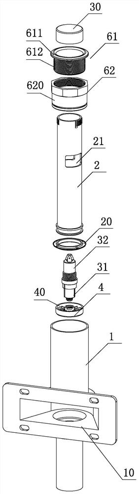
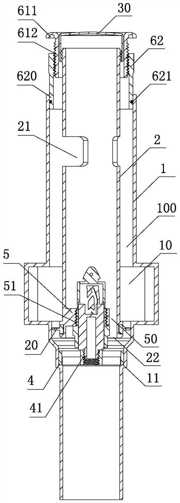
[0026] The drainage and overflow integrated drain device provided by the present invention includes a switch and a drain tube 1. The drain tube is a straight tubular cylinder with a drain and overflow port 10 on the wall; the normal drainage and overflow of the sanitary ware pass through this port.

[0027] A liftable rigid connecting pipe 2 is provided in the water tank 1, and the rigid connecting pipe 2 is connected with the switch so as to be operated to descend and rise. There is a gap 100 between the rigid connecting pipe 2 and the water tank 1, The rigid connecting pipe 2 and the water tank 1 are generally arranged concentrically, and the outer diameter of the rigid connecting pipe 2 is smaller than that of the water tank 1, so the gap 100 is an annular gap with a certain height.

[0028] The lower part of the rigid connecting pipe 2 is provided with a sealing member 20, which is used as the opening and closing pa...

Embodiment 2

[0034] Embodiment 2, with reference to Figure 4 , and combined with the reference Figure 1-3 .

[0035] The structure of the present invention is not only suitable for the switch to be installed on the lower end of the rigid connecting pipe 2, but also suitable for the switch to be installed on the upper end of the rigid connecting pipe 2. In this embodiment, the switch is installed on the upper end of the rigid connecting pipe 2 as an example:

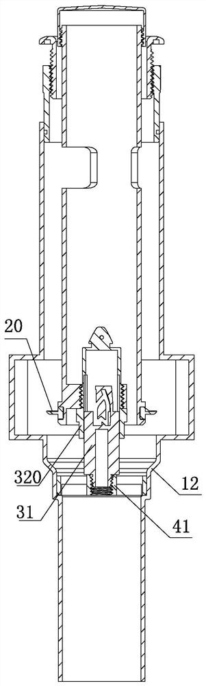
[0036] Described switch comprises fixed part 31b and lift part 32b, and the cooperation relation of fixed part 31b and lift part 32b is the same as embodiment 1, only fixed part 31b is provided with axial through hole, and the integral body of lift part 32b is from the axis of fixed part 31b. Pass through the through hole, and connect with the upper end of the lifting rigid connecting pipe 2 at the lower end. The upper end of the lifting portion 32b is connected to the button 30b.

[0037] When the lifting rigid connecting pipe ...

Embodiment 3

[0044] Embodiment 3, with reference to Figure 5-7 , and combined with the reference Figure 1-3 .

[0045] This embodiment is basically the same as Embodiment 1. Only in the installation method of the drainer, the nut and its lower connecting cylinder are all used as the appearance part 62c, and the upper part of the component 62c is threaded with the central connecting cylinder 611 using internal threads, and the drain cylinder 1 is inserted into the inside of the component 62c, and The socket in the non-embodiment 1 is outside the connecting cylinder 620 . From an installation point of view, this is easier to install and the appearance of the part is easier to handle.

[0046] The other parts of this embodiment are the same as Embodiment 1, and the corresponding parts and structures adopt the same Figure 1-3 The same reference numerals.


PUM


Abstract

The invention provides a drainage and overflow integrated drainer, which comprises a switch and a drainage cylinder, wherein the drainage cylinder is provided with a drainage and overflow port; a liftable rigid connecting pipe is arranged in the drainage cylinder, the rigid connecting pipe is connected with the switch, a gap is formed between the rigid connecting pipe and the drainage cylinder, a sealing piece is arranged on the lower portion of the rigid connecting pipe, an overflow port is formed in the upper portion of the rigid connecting pipe, and the gap is communicated with the drainage overflow port and the overflow port. An overflow water outlet is formed in the lower end of the rigid connecting pipe. The problems of tedious installation and water leakage hidden dangers caused by external connection of an overflow pipe are avoided. Moreover, the flow area of the overflow channel is larger, the overflow guarantee is safer, different overflow depth requirements can be met by flexibly forming the overflow holes in the rigid connecting pipe at different heights, and compared with the conventional structure, the overflow channel is more convenient and flexible and has stronger universality.

Description

technical field [0001] The invention relates to a drainage and overflow integrated drain device. Background technique [0002] At present, the hidden structure drain in the sanitary ware market is operated by a push switch. This kind of drain needs an external overflow pipe, which increases the manufacturing cost, is cumbersome to install, and has the hidden danger of water leakage. Contents of the invention [0003] The technical problem to be solved by the present invention is to provide an integrated drainage and overflow drain, which does not need to overflow through an external bypass, which is convenient for installation and avoids the hidden danger of water leakage caused by overflow discharge. For this reason, the present invention adopts following technical scheme: [0004] The drainage and overflow integrated drain device includes a switch and a water tank, and the water tank is provided with a drainage and overflow port; it is characterized in that a liftable ...

Claims


Application Information

Patent Timeline
Patent Type & Authority Applications(China)
IPC IPC(8): E03C1/232E03C1/28
Inventor 岑迪峰
Owner NINGBO BOSHENG PLUMBING CO
Why Eureka
Try Eureka