
Superconducting magnetic suspension track structure

A magnetic levitation and track technology, applied in the direction of track, road, magnetic attraction or thrust holding device, etc., can solve the problems of cumbersome and difficult installation of permanent magnet track, and achieve the effect of avoiding cumbersome and difficult installation, easy installation and simple structure

Pending Publication Date: 2022-04-15
INST OF ELECTRICAL ENG CHINESE ACAD OF SCI
View PDF0 Cites 0 Cited by
  • Summary
  • Abstract
  • Description
  • Claims
  • Application Information

AI Technical Summary

Problems solved by technology

[0003] The purpose of the present invention is to provide a superconducting magnetic levitation track structure, which solves the defect of cumbersome and difficult installation of permanent magnet tracks in the prior art, and provides a simpler and more convenient low-cost structure

Method used


Image

  • Superconducting magnetic suspension track structure
  • Superconducting magnetic suspension track structure
  • Superconducting magnetic suspension track structure

Examples


Embodiment 1

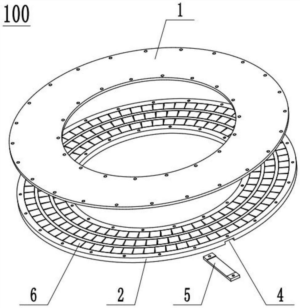
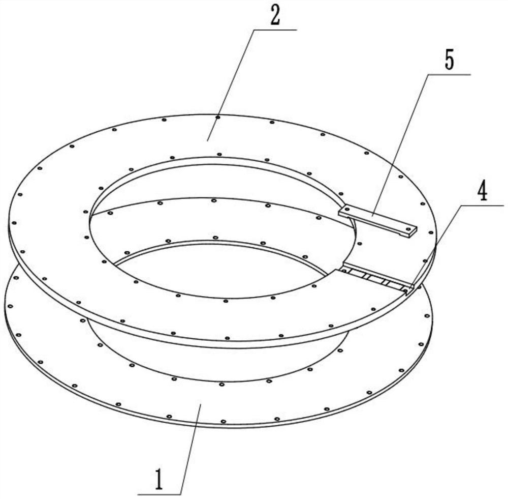
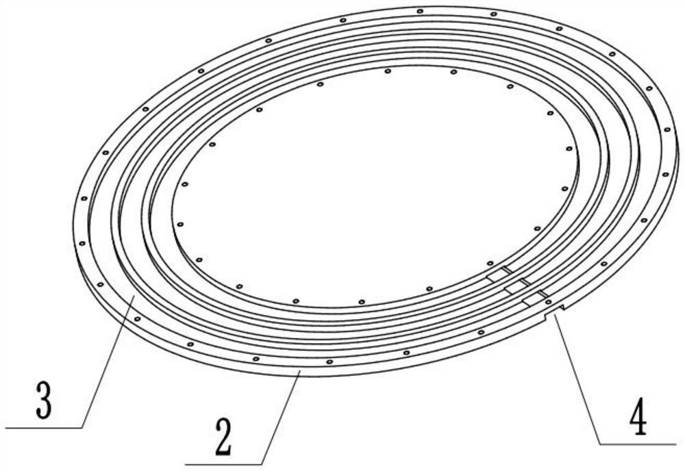
[0029] Such as Figure 1-Figure 4 As shown: the present embodiment provides a superconducting maglev track structure 100, including track body 7 and several permanent magnets 6, each permanent magnet 6 is a square NdFeB permanent magnet with the same size and grade, and track body 7 is provided with At least one track cavity 8, each track cavity 8 is parallel, and some permanent magnets 6 are all arranged in each track cavity 8, and each permanent magnet 6 can slide along the length direction of the track cavity 8, in the same track cavity 8 The magnetic poles of each permanent magnet 6 are the same, and the magnetic field is relatively uniform. The force between adjacent permanent magnets 6 in the same track cavity 8 is a repulsive force, and the magnetization direction of each permanent magnet 6 corresponds to the track body 7 of the permanent magnet 6. The surface of the superconducting magnetic levitation track structure 100 is perpendicular to the surface, and the magneti...

Embodiment 2

[0037] Such as Figure 5-Figure 6 As shown, the difference between this embodiment and the first embodiment is that the track body 7 is integrally formed, and the track body 7 is made of a flexible material into a deformable shape, and the flexible material is a deformable material with a certain strength such as rubber.

[0038] In this embodiment, one end of the track body 7 is detachably connected to the other end of the track body 7 , and one end of the track body 7 is provided with an opening for putting the permanent magnet 6 into the track cavity 8 .

[0039] Such as Figure 5 As shown, when the two ends of the track body 7 are not connected, the track body 7 is straight; after the permanent magnet 6 is put into the track body 7, the track body 7 is twisted, and one end of the track body 7 is connected to the track body 7. The other ends are connected to form a superconducting maglev track structure 100 .

[0040]When manufacturing the superconducting maglev track str...


PUM


Abstract

The invention discloses a superconducting magnetic suspension track structure, and relates to the technical field of superconducting electromagnetic application, the superconducting magnetic suspension track structure comprises a track body and a plurality of permanent magnets, the track body is internally provided with at least one track cavity, each track cavity is internally provided with a plurality of permanent magnets, each permanent magnet can slide along the length direction of the track cavity, and the permanent magnets are arranged in the track cavity. The magnetic poles of the permanent magnets in the same track cavity are the same, and the magnetizing direction of each permanent magnet is perpendicular to the surface of the track body corresponding to the permanent magnet. According to the invention, the defect that a permanent magnet track is tedious and difficult to install in the prior art is overcome, a structure which is simpler, more convenient and lower in cost is provided, and a superconducting magnetic suspension track structure which is lighter and / or deformable is realized.

Description

technical field [0001] The invention relates to the technical field of superconducting electromagnetic applications, in particular to a superconducting magnetic levitation track structure. Background technique [0002] High-temperature superconducting maglev has become more and more known to the public. It uses the magnetic flux pinning and quantum locking effects of high-temperature superconductors to make superconductors levitate along the permanent magnet track. However, the existing superconducting maglev track mainly fixes the permanent magnet in two ways: (1) using super glue to stick the permanent magnet on the track; (2) using magnetic force to attach the permanent magnet to the ferromagnetic track. The first method needs to paste the permanent magnets one by one while overcoming the repulsive force between the permanent magnets, which is very difficult. In the event of poor adhesion, permanent magnet arrangement error or uneven magnetic field of individual permanen...

Claims


Application Information

Patent Timeline
Patent Type & Authority Applications(China)
IPC IPC(8): E01B25/30H02N15/00
Inventor 黄大兴丁发柱古宏伟董浩王锴
Owner INST OF ELECTRICAL ENG CHINESE ACAD OF SCI
Learn More