Gravity compensator with low rigidity and large suspension force

A technology of gravity compensation and levitation force, which is applied in the direction of magnetic attraction or thrust holding device, electrical components, etc., can solve the problems of high levitation stiffness and low levitation force of magnetic levitation gravity compensator, and achieve low levitation stiffness and large levitation force , the effect of increasing the magnetic field strength

Active Publication Date: 2020-06-19
CHONGQING UNIV +1
View PDF9 Cites 10 Cited by
  • Summary
  • Abstract
  • Description
  • Claims
  • Application Information

AI Technical Summary

Problems solved by technology

However, the magnetic levitation gravity compensator has low levitation force and high levitation stiffness

Method used


Image

  • Gravity compensator with low rigidity and large suspension force
  • Gravity compensator with low rigidity and large suspension force
  • Gravity compensator with low rigidity and large suspension force

Examples


Embodiment 1

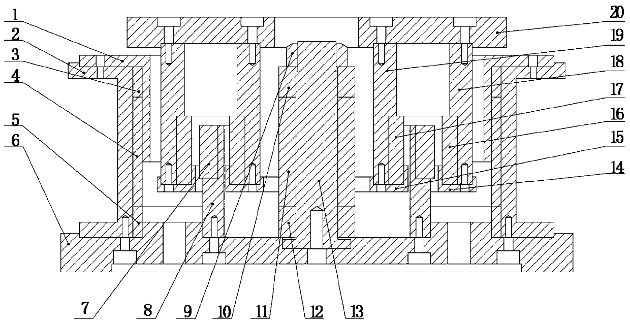
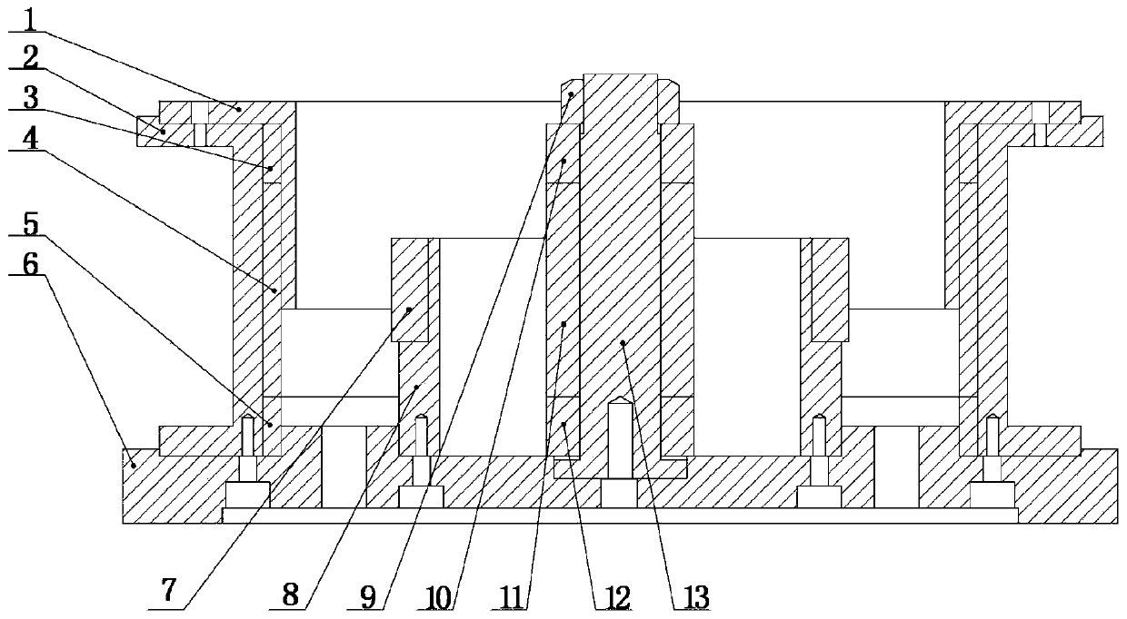
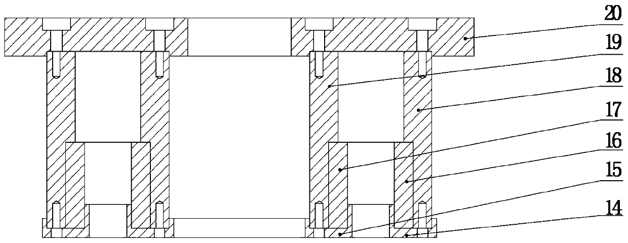
[0033] Such as Figure 1-Figure 8 As shown: this embodiment provides a gravity compensator with low stiffness and large levitation force, including a stator part and a mover part, and the stator part includes a stator fixing structure, a permanent magnet in the inner ring of the stator, a coil 7 and a permanent magnet in the outer ring of the stator , the stator inner ring permanent magnet, the coil 7 and the stator outer ring permanent magnet are all fixed on the stator fixed structure, the mover part includes the mover fixed structure, the mover inner ring permanent magnet 17 and the mover outer ring permanent magnet 16, the mover Both the permanent magnets 17 of the inner ring and the permanent magnets 16 of the outer ring of the mover are fixed on the fixed structure of the mover. The permanent magnets 17 of the inner ring of the mover are arranged on the inner side of the permanent magnets 16 of the outer ring of the mover. The permanent magnet 17, the coil 7, the permane...

Embodiment 2

[0055] The difference between this embodiment and Embodiment 1 is that the first stator inner ring permanent magnet 10 and the first stator outer ring permanent magnet 3 are magnetized by radiation from outside to inside, and the third stator inner ring permanent magnet 12 and the third stator inner ring permanent magnet 12 are magnetized from outside to inside. The permanent magnets 5 of the stator outer ring are all radiated and magnetized from the inside to the outside, the magnetization direction of the second stator inner ring permanent magnet 11 is from top to bottom, and the magnetization direction of the second stator outer ring permanent magnet 4 is from bottom to top, Both the permanent magnets 17 of the inner ring of the mover and the permanent magnets 16 of the outer ring of the mover are magnetized radially from outside to inside, and the equivalent magnetization direction of the coil 7 is from top to bottom.


PUM


Abstract

The invention discloses a gravity compensator with low rigidity and large suspension force. A stator part comprises a stator inner ring permanent magnet, a coil and a stator outer ring permanent magnet; a mover part comprises a mover inner ring permanent magnet and a mover outer ring permanent magnet, the stator inner ring permanent magnet, the mover inner ring permanent magnet, the coil, the mover outer ring permanent magnet and the stator outer ring permanent magnet are sequentially arranged from inside to outside, gaps are formed between them, and the stator part and the mover part interactto generate suspension force. The inner ring and the outer ring of the stator respectively comprise three layers of permanent magnets in the axial direction such that the magnetic field intensity isincreased, and the suspension force generated by the gravity compensator is large; meanwhile, the magnetizing directions of an upper layer and a lower layer of the three layers of permanent magnets are opposite such that the magnetic field is more uniform, the suspension force is close to linearity, the suspension rigidity is reduced, the gravity of a load can be effectively compensated, the positioning of the bearing platform is realized, and the influence of internal and external disturbance sources on the load is reduced.

Description

technical field [0001] The invention relates to the technical field of gravity compensators, in particular to a gravity compensator with low stiffness and large suspension force. Background technique [0002] With the continuous development of modern industry, ultra-precision processing occupies an increasingly important position in many fields such as machinery, electronics, light industry and national defense. Lay a solid foundation. As a typical representative of ultra-precision processing technology, lithography machines have played a vital role in the development of semiconductor technology. However, during the exposure process, the silicon wafer carrier table of the lithography machine will be disturbed by the external noise of the internal power device, thereby affecting its positioning accuracy. The gravity compensation device is a new type of passive mechanism proposed to solve this problem. By compensating the gravity of the load, the positioning of the silicon w...

Claims


Application Information

Patent Timeline
Patent Type & Authority Applications(China)
IPC IPC(8): H02N15/00
CPCH02N15/00
Inventor 蒲华燕赵晶雷丁基恒王敏孙翊罗均谢志江彭艳谢少荣
Owner CHONGQING UNIV
Why Eureka
Try Eureka