
Induction melting cold crucible with full suspension and strong stirring ability

A technology of induction melting and cold crucible, applied in the direction of crucible furnace, stirring device, furnace, etc., can solve the problems of affecting alloy uniformity, waste, weak electromagnetic stirring ability, etc., and achieve the goal of reducing product quality, reducing energy consumption, and preventing pollution Effect

Pending Publication Date: 2021-02-23
宝鸡华煜鼎尊材料技术有限公司
View PDF8 Cites 1 Cited by
  • Summary
  • Abstract
  • Description
  • Claims
  • Application Information

AI Technical Summary

Problems solved by technology

However, the electromagnetic fields formed by the induction coils located on the side wall and bottom of the crucible interfere with each other, resulting in uneven electromagnetic fields inside the crucible body, uneven heating and stirring of the charge, and affecting the uniformity of the alloy.
In addition, when the molten metal flows out from the sprue, the force of the induction coil is lost, and the molten metal cannot flow out evenly along a certain trajectory, but it has great randomness, resulting in the molten metal not being able to accurately enter the mold inlet, resulting in waste
[0008] In addition, although there is electromagnetic stirring in the existing suspension smelting technology, the electromagnetic stirring ability is weak, and it is not possible to fully homogenize the molten pool components.

Method used


Image

  • Induction melting cold crucible with full suspension and strong stirring ability
  • Induction melting cold crucible with full suspension and strong stirring ability
  • Induction melting cold crucible with full suspension and strong stirring ability

Examples


Embodiment Construction

[0046] Exemplary embodiments of the present disclosure will be described in more detail below with reference to the accompanying drawings. Although exemplary embodiments of the present disclosure are shown in the drawings, it should be understood that the present disclosure may be embodied in various forms and should not be limited to the embodiments set forth herein. Rather, these embodiments are provided so that the present disclosure can be more thoroughly understood and the scope of the present disclosure can be fully conveyed to those skilled in the art.

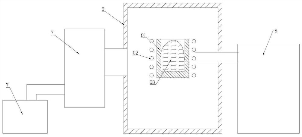
[0047] like image 3 As shown, the cold crucible vacuum induction melting equipment includes vacuum furnace body 6, vacuum unit 7, induction power supply 8 and other components. The split cold crucible is placed in the vacuum furnace body 6, and the oscillating current output by the high-frequency induction power supply 8 is sent to the induction coil surrounding the crucible 1, and the generated electromagnetic field ...


PUM


Abstract

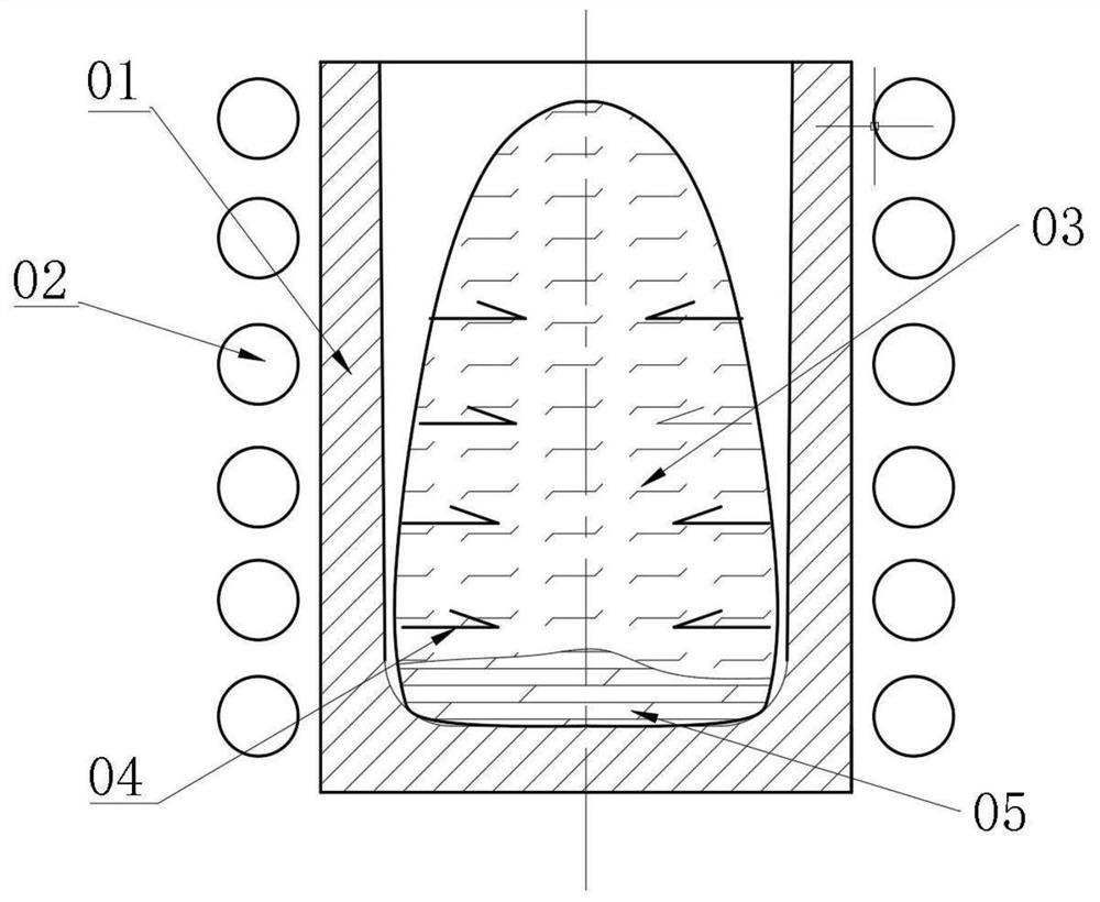
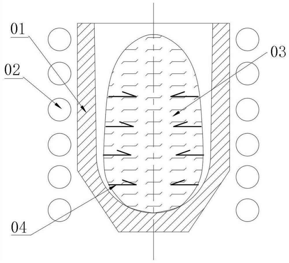
The invention discloses an induction melting cold crucible with full suspension and strong stirring ability. The induction melting cold crucible comprises a crucible body, a main induction coil, a bottom induction coil, a main magnetic field disturbance cylinder and a bottom magnetic field disturbance cylinder, wherein the main induction coil is arranged on the outer side surface of the crucible body, and radial suspension force is applied to a molten pool through the main induction coil, so that the molten pool can be separated from the side surface of the crucible body; the bottom inductioncoil is arranged at the bottom of the crucible; upward suspension force is applied to the bottom of the molten pool through a planar spiral bottom induction coil or a spiral conical induction coil viathe bottom induction coil, so that the bottom of the molten pool is separated from the inner bottom surface of the crucible, full suspension of the molten pool is realized, a smelting temperature isincreased, the uniformity of alloy components is improved, and skull formation is prevented. Besides, a spiral small conical or cylindrical induction coil is arranged at the bottom of the crucible, acting force is applied to cast molten metal, molten metal is located in the middle all the time, and casting is accurate.

Description

technical field [0001] The invention relates to a cold crucible for induction smelting with full suspension and strong stirring capability, in particular to a cold crucible which uses an electromagnetic field to improve the suspension effect during the suspension smelting process, and belongs to the technical field of smelting. Background technique [0002] Cold crucible vacuum induction smelting (vacuum electromagnetic levitation smelting) is one of the most advanced smelting technologies. It is similar to vacuum intermediate frequency induction smelting. It uses electromagnetic fields to heat metals in a vacuum or inert gas environment to complete the smelting process. It is a non-gas pollution smelting technology. Compared with vacuum intermediate frequency induction melting, cold crucible vacuum induction melting uses electromagnetic levitation force to make the molten metal pool in a suspended state in the crucible, avoiding the pollution of the crucible material to the...

Claims


Application Information

Patent Timeline
IPC IPC(8): F27B14/06F27B14/08F27B14/10F27D27/00
CPCF27B14/061F27B14/10F27B14/0806F27D27/00F27B2014/108F27B2014/0825
Inventor 李佳李庚
Owner 宝鸡华煜鼎尊材料技术有限公司
Learn More