Self-stabilization passive magnetic bearing for generator of power grid

A magnetic bearing, self-stabilizing technology, applied in the directions of bearings, shafts and bearings, mechanical equipment, etc., can solve the problems of the combination configuration of passive magnetic bearings, the inability to achieve full suspension with five degrees of freedom, the intricate power grid technology, etc., to achieve freedom The effect of full suspension, weight reduction and volume reduction

Active Publication Date: 2016-01-27
北京高孚动力科技有限公司
View PDF6 Cites 0 Cited by
  • Summary
  • Abstract
  • Description
  • Claims
  • Application Information

AI Technical Summary

Problems solved by technology

[0002] The power grid technology is complicated. In the grid power system, the generator is one of the important links. In order to improve the efficiency of the generator, improve the technical level of the generator, and achieve the national goal of energy conservation and environmental protection, the development of magnetic levitation motors has developed rapidly in recent years. Traditional The magnetic levitation motor system realizes the levitation of five degrees of freedom, which needs to adopt the combination of active magnetic bearing and passive magnetic bearing. We know that the magnetic levitation bearing is divided into active type and passive type. The active magnetic levitation bearing is superimposed on the basis of the bias magnetic field. The magnetic suspension bearing is made by controlling the magnetic field generated by the coil. The passive magnetic suspension bearing is a magnetic suspension bearing made of only the permanent magnetic field. The existing passive magnetic bearings are divided into suction type and repulsion type passive magnetic bearings, most of which use stator permanent magnets The interaction with the permanent magnet of the rotor in the air gap produces the force required for stability. According to Enshoe's theorem, a single passive magnetic bearing cannot achieve full suspension with five degrees of freedom, but this theorem does not apply to the combined configuration of passive magnetic bearings. To illustrate, the current single passive magnetic bearing really cannot achieve full suspension with five degrees of freedom

Method used


Image

  • Self-stabilization passive magnetic bearing for generator of power grid
  • Self-stabilization passive magnetic bearing for generator of power grid
  • Self-stabilization passive magnetic bearing for generator of power grid

Examples


Embodiment Construction

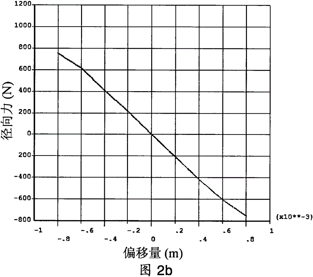
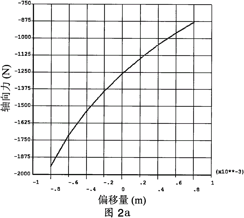
[0017] figure 1 It is a pair of single-group passive magnetic bearings described in the present invention, in the figure a is the magnetization angle, D i Be the internal diameter of permanent magnet ring, be 250mm in the present embodiment, D o Be the external diameter of permanent magnet ring, be 350mm in the present embodiment, L is the axial length of permanent magnet ring, be 100mm in the present embodiment, the thickness of each permanent magnet ring is 100mm in the present embodiment, among the figure d is the length of the air gap, which is 1mm in this embodiment. When one of the permanent magnet rings moves axially, the resulting displacement is called the offset, and the positive movement along the z-axis or the positive direction of the y-axis is positive. Movement along the negative z-axis or negative y-axis is negative.

[0018] When the magnetization angle a of the permanent magnet ring is 15 degrees, the axial force curve and radial force curve of a single per...


PUM


Abstract

The invention relates to a non-contact magnetic bearing, in particular to a self-stabilization passive magnetic bearing for a power grid. The self-stabilization passive magnetic bearing can be used as a non-contact support of rotary components in generators for the small power grid and other mechanical equipment. The passive magnetic bearing is composed of two sets of passive magnetic bearing pairs. Each set of passive magnetic bearing pair is composed of two permanent magnet rings. A stator part and a rotor part are formed by the passive magnetic bearing pairs together. A magnetic air gap is formed between the stator part and the rotor part. The magnetization direction of each permanent magnet ring is specially required. A sensor system, a control coil and a power amplifier circuit needed by the control coil are omitted, and especially, the structural form of the passive magnetic bearing pairs is adopted so that five-freedom-degree full suspension of the passive magnetic bearing can be achieved.

Description

technical field [0001] The invention relates to a non-contact magnetic suspension bearing, in particular to a self-stabilizing passive magnetic bearing structure for power grid generators, which can realize non-contact support of rotating parts such as small generators and motors for power grids. Background technique [0002] The power grid technology is complicated. In the grid power system, the generator is one of the important links. In order to improve the efficiency of the generator, improve the technical level of the generator, and achieve the national goal of energy conservation and environmental protection, the development of magnetic levitation motors has developed rapidly in recent years. Traditional The magnetic levitation motor system realizes the levitation of five degrees of freedom, which needs to adopt the combination of active magnetic bearing and passive magnetic bearing. We know that the magnetic levitation bearing is divided into active type and passive ty...

Claims


Application Information

Patent Timeline
Patent Type & Authority Applications(China)
IPC IPC(8): F16C32/04
Inventor 俱子研
Owner 北京高孚动力科技有限公司
Why Eureka
Try Eureka