Eureka AIR delivers breakthrough ideas for toughest innovation challenges, trusted by R&D personnel around the world.

Stator permanent magnet-biased sheet-shaped inner-rotor bearingless asynchronous rotor

A technology of permanent magnet bias and asynchronous motors, which is applied in asynchronous induction motors, electromechanical devices, electrical components, etc., and can solve problems such as control strategy constraints, large magnetic circuit reluctance, and complex structures.

Active Publication Date: 2018-10-26
HUAIYIN INSTITUTE OF TECHNOLOGY
View PDF2 Cites 2 Cited by
  • Summary
  • Abstract
  • Description
  • Claims
  • Application Information

AI Technical Summary

Problems solved by technology

In this way, the ordinary bearingless motor is not only subject to many restrictions on the control strategy, but also has a very complicated structure.
When the axial length of the rotor of a bearingless motor is small compared to its diameter, the rotor is passively stable in the axial direction, and stable suspension only needs to control the two radial degrees of freedom of the rotor. This special bearingless motor is called a sheet Shaped bearingless motor has become one of the hotspots in the field of bearingless motor research today, and a variety of structural sheet bearingless permanent magnet motors have been studied. The existence of rotor permanent magnets leads to large reluctance in the magnetic circuit and high power consumption. , and the mechanical strength of the rotor is low, it is difficult to achieve higher speed and higher power operation

Method used


Image

  • Stator permanent magnet-biased sheet-shaped inner-rotor bearingless asynchronous rotor
  • Stator permanent magnet-biased sheet-shaped inner-rotor bearingless asynchronous rotor
  • Stator permanent magnet-biased sheet-shaped inner-rotor bearingless asynchronous rotor

Examples


Embodiment Construction

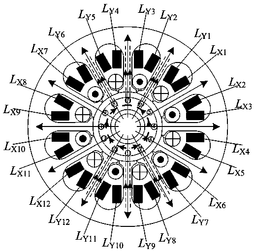
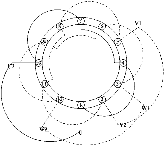
[0018] Such as Figures 1 to 6 As shown, a three-phase motor with 12 stator slots, 1 suspension winding pole pair, and 2 torque winding pole pairs is used as an example to describe in detail:

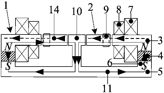
[0019] A bearingless asynchronous motor with a stator permanent magnet bias plate inner rotor, including a stator 1, a rotor core 2 located in the inner ring of the stator 1, the stator 1 includes a stator core 3, an axially magnetized annular permanent magnet 4 and an iron core Bridge 5, the main body of the iron core bridge 5 is a circular plate, and the edge of the circular plate is provided with a circle of upwardly protruding annular boss 6, and the annular permanent magnet 4 is laminated and fitted on the annular boss 6. The lower end surface of the stator core 3 is laminated with the upper side of the annular permanent magnet 4, and a stator slot is opened on the stator core 3, and a suspension winding 7 and a torque winding 8 are arranged in the stator slot; the iron core The m...


PUM


Abstract

The invention discloses a stator permanent magnet-biased sheet-shaped inner-rotor bearingless asynchronous rotor. The stator permanent magnet-biased sheet-shaped inner-rotor bearingless asynchronous rotor comprises a stator and a rotor, wherein the rotor is arranged in an inner circle of the stator, the stator comprises a stator core, an axially-magnetized annular permanent magnet and an iron corebridge, a stator groove is formed in the stator core, a suspension winding and a torque winding are arranged in the stator groove, a T-shaped cylindrical boss is arranged at a middle part of the ironcore bridge and protrudes inwards, the rotor is a hollow thin circular post, an outer side air gap exists between the rotor and the stator core, an inner side air gap exists between the rotor and theT-shaped boss, a rotor groove is formed in a surface of the outer side air gap of the rotor, a guide strip is casted into the groove or a winding is wound around the groove, and the pole pairs of thewinding are different from those of the suspension winding. The stator permanent magnet-biased sheet-shaped inner-rotor bearingless asynchronous rotor is compact in structure and is simple to control, no coupling is generated between a suspension force and torque, and axial passive control and radial active control are performed.

Description

technical field [0001] The invention relates to the technical field of motor manufacturing, in particular to a bearing-less asynchronous stator permanent magnet bias plate inner rotor with compact structure, simple control, independent suspension control and torque control, radial active control, and axial passive control motor. Background technique [0002] At present, the bearingless asynchronous motor is by superimposing an additional set of suspension windings on the torque winding of the stator slot of the traditional asynchronous motor, and the two sets of windings are respectively powered by a three-phase AC power supply with the same frequency to generate the rotating suspension winding magnetic field and torque. The winding magnetic field, and the number of pole pairs of the suspension winding magnetic field is P B , the torque winding magnetic field is P M , between the two only satisfy P B = P M When the relationship between ±1, the stable and controllable...

Claims


Application Information

Patent Timeline
IPC IPC(8): H02K17/16H02K3/28
CPCH02K3/28H02K17/165
Inventor 张涛刘欣凤莫丽红倪伟丁祖军武莎莎
Owner HUAIYIN INSTITUTE OF TECHNOLOGY
Why Eureka
Eureka Blog
Learn More