Connecting structure for optical fiber connector

An optical fiber connector and connection structure technology, applied in the field of communication, can solve the problems of large size, unevenness, and the connector can not be completely matched, and achieve the effect of simple positioning and fixing, and simple connection

Inactive Publication Date: 2022-04-01
ADF FIBERCOM LTD
View PDF6 Cites 0 Cited by
  • Summary
  • Abstract
  • Description
  • Claims
  • Application Information

AI Technical Summary

Problems solved by technology

However, during the sanding process, the surface polished by the sandpaper is not flat. In some places, the size of the sanded off is too large, and some are uneven, and the plane of the polished surface is not perpendicular to the angular line of the connector, so that the two connectors The butt joints do not fit perf

Method used


Image

  • Connecting structure for optical fiber connector
  • Connecting structure for optical fiber connector
  • Connecting structure for optical fiber connector

Examples


Example Embodiment

[0017] In order to further illustrate the various embodiments, the present invention provides accompanying drawings, which are part of the disclosure of the present invention, and are mainly used to illustrate the embodiments, and can be used in conjunction with the relevant descriptions in the specification to explain the operation principles of the embodiments. For these, those of ordinary skill in the art will understand other possible implementations and the advantages of the present invention. Components in the figures are not drawn to scale, and similar component symbols are generally used to represent similar components.

[0018] The specific embodiments of the present invention will be further described below with reference to the accompanying drawings. It should be noted here that the descriptions of these embodiments are used to help the understanding of the present invention, but do not constitute a limitation of the present invention. In addition, the technical fea...


PUM


Abstract

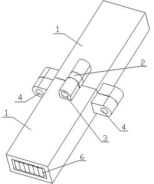
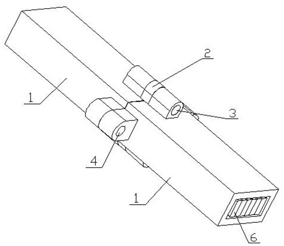
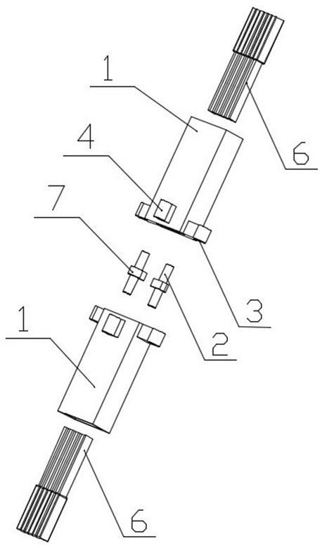
The invention discloses a connecting structure for optical fiber connectors, which comprises two optical fiber connectors with optical fibers, a positioning piece and a fixing piece, and is characterized in that each optical fiber connector is provided with two positioning holes and two fixing holes, and an AR film is sprayed or smeared between the two optical fiber connectors so as to increase the light transmittance; the positioning piece is inserted into the positioning holes of the two optical fiber connectors respectively, the fixing piece is inserted into the fixing holes of the two optical fiber connectors respectively and fixes the two optical fiber connectors together, and the positioning piece penetrates through the positioning hole of one optical fiber connector and then penetrates through the positioning hole of the other optical fiber connector to enable the two optical fiber connectors to be aligned. The two positioning holes and the two fixing holes are formed in the same side of the end face to be polished. According to the optical fiber connector, the two positioning holes and the two fixing holes are symmetrically formed in the optical fiber connector, so that the end face of the connector can be simply positioned and fixed, meanwhile, the structure of the connector is also suitable for a polishing process for polishing small equipment, and the connection of the two connectors is simple and convenient.

Description

technical field [0001] The invention relates to the technical field of communication, in particular to a connection structure for an optical fiber connector. Background technique [0002] With the continuous progress of the optical communication industry, more and more optical fibers are used. However, fiber optic connectors are very sensitive to dust. Therefore, fiber optic connectors should try to avoid dust from entering. However, in the current connection process of the optical fiber connector, the end face of the optical fiber connector must be polished flat with sandpaper, and then a layer of AR film is sprayed to make an anti-reflection coating. However, during the sanding process, the surface polished by the sandpaper is not flat. In some places, the size of the sanded off is too large, and some are uneven, and the plane of the polished surface is not perpendicular to the angular line of the connector. The butt joints cannot be completely matched. This requires spe...

Claims


Application Information

Patent Timeline
IPC IPC(8): G02B6/38
Inventor 王网喜冷小冬叶聿村
Owner ADF FIBERCOM LTD
Why Eureka
Try Eureka