Method and membrane module for the energy-efficient oxygen generation during biomass gasification

Active Publication Date: 2017-08-08
FRAUNHOFER GESELLSCHAFT ZUR FOERDERUNG DER ANGEWANDTEN FORSCHUNG EV
View PDF32 Cites 2 Cited by
  • Summary
  • Abstract
  • Description
  • Claims
  • Application Information

AI Technical Summary

Benefits of technology

[0017]Direct heating of the membrane module with the synthesis gas from the biomass gasification results in a simple connection to the gasification installation and is characterized by a very fast thermal response behavior and an uncomplicated control behavior. In this way, the temperature in the membrane module can be increased to its optimal operating temperature independent of the available temperature level of the gasification process. Accordingly, when using the directly gas-heated membrane module, plant-specific peculiarities of the biomass gasification plant play only a subordinate part such that incorporation in existing plants is greatly facilitated. Further, the supplied energy of the synthesis gas is exploited to the optimal extent owing to the combustion inside the membrane module.
[0018]The effect of corrosive gas constituents such as CO2 or SO2 on the MIEC membranes is extensively inhibited or limited through a constructive configuration of the gas flow. According to the invention, the incoming preheated fresh air is initially guided within protective tubes along the membrane tubes located therein and only then enters the actual combustion space. To this end, the outlet orifice of the protective tubes is dimensioned in such a way that the fresh air entering the combustion space reaches a velocity of at least 0.2 m/s within the gas outlet orifice. Gaseous combustion products are largely kept away from the membrane material in this way. Accordingly, the combustion of the synthesis gas takes place spatially and temporally only after fresh air contacts the membrane; that is, the combustion takes place with the oxygen-depleted air. Accordingly, the unaffected oxygen partial pressure of the incoming fresh air and, therefore, the full driving force is available for the membrane separation process on the feed side of the membrane, which results in a maximum oxygen production

Problems solved by technology

However, this heating should only meet less than 20%, typically less than 10% and, under

Method used


Image

  • Method and membrane module for the energy-efficient oxygen generation during biomass gasification
  • Method and membrane module for the energy-efficient oxygen generation during biomass gasification
  • Method and membrane module for the energy-efficient oxygen generation during biomass gasification

Examples


Example

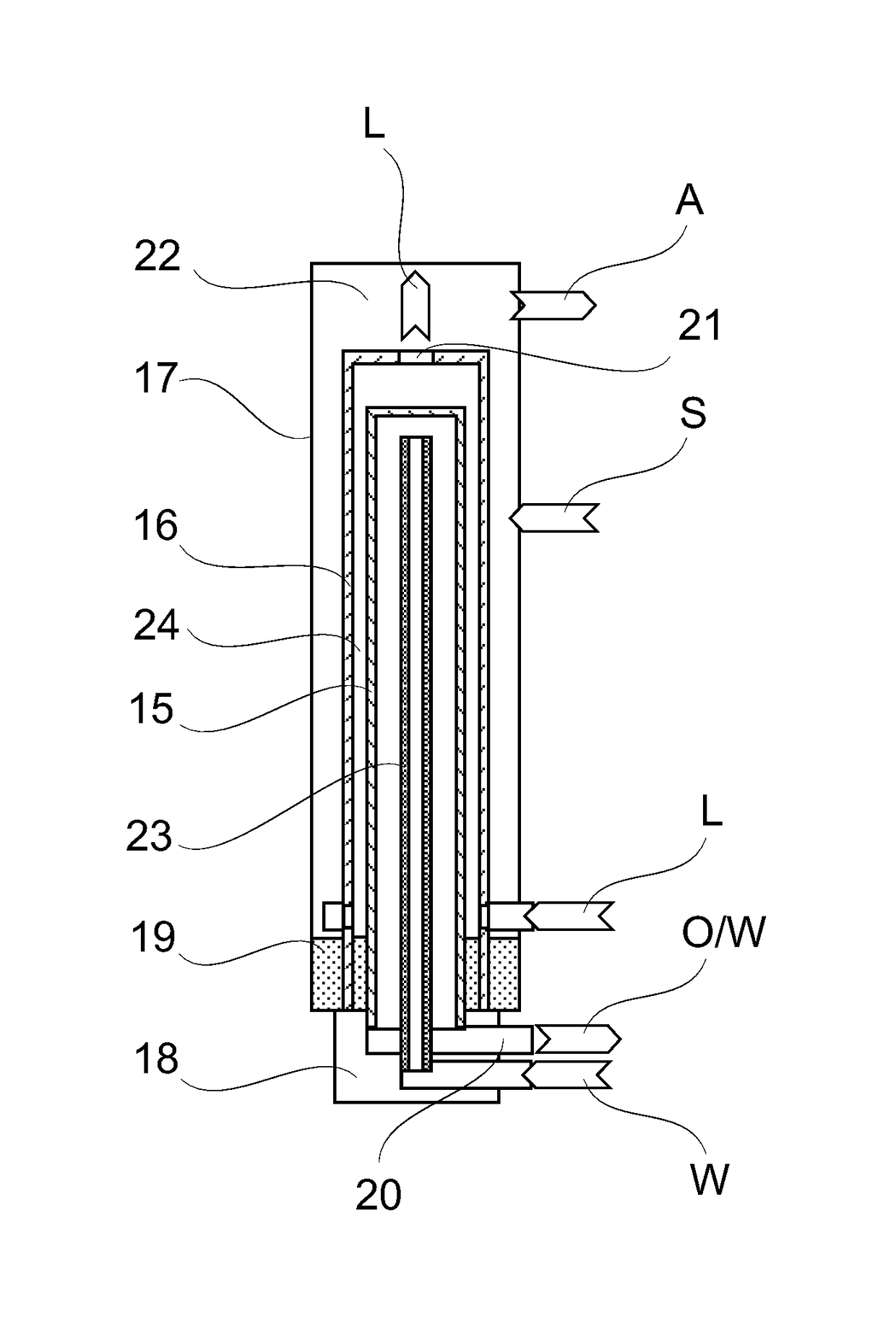
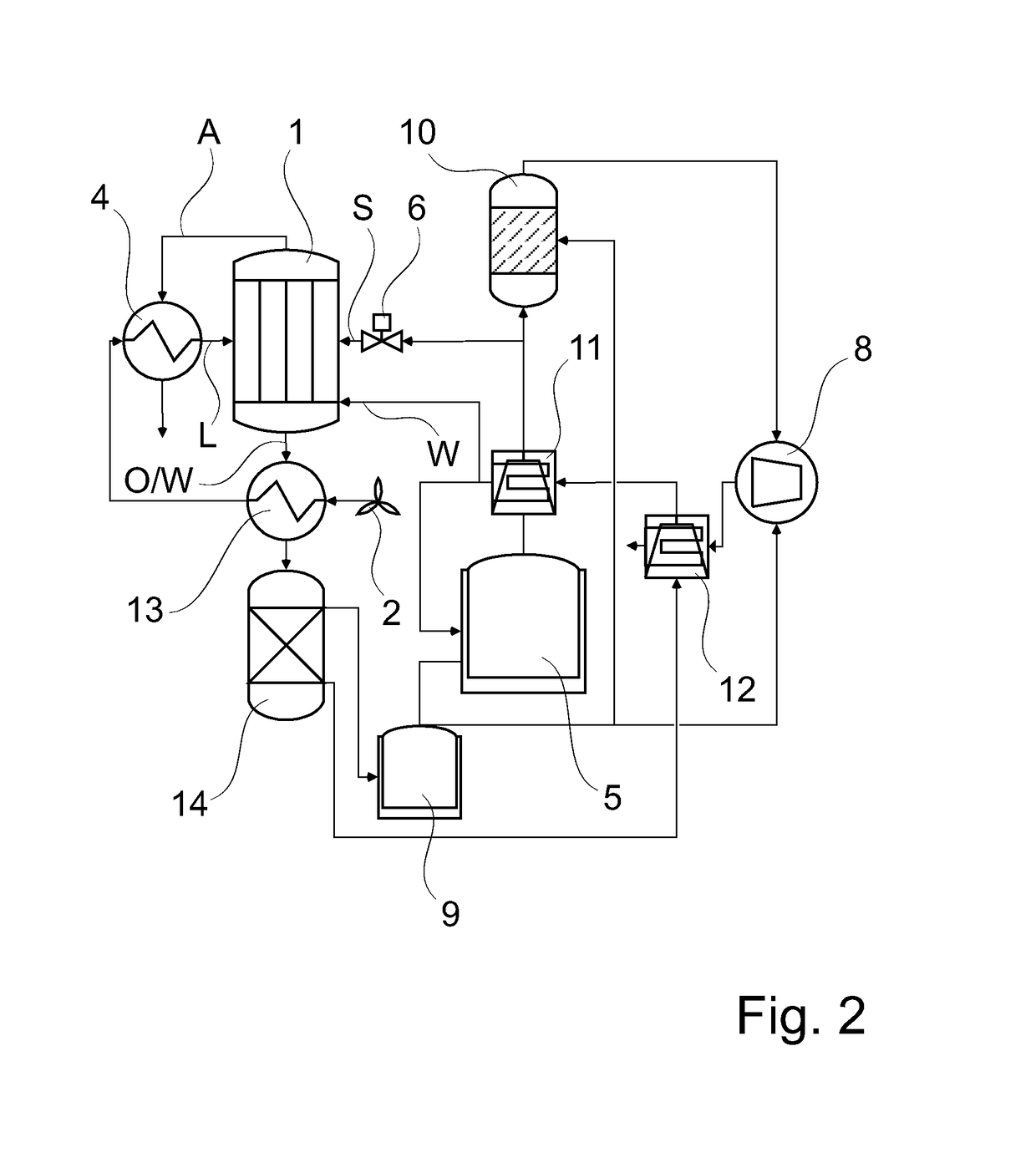
[0027]FIG. 1 shows an integrated oxygen generation in the biomass gasification through vacuum suction of an oxygen membrane module which is directly heated by synthesis gas and has a minimized electrical power requirement, including the essential components thereof.

[0028]The membrane module 1 for oxygen generation in the biomass gasification is outfitted with 2500 BSCF (Ba0.5Sr0.5Co0.8Fe0.2O3-δ) membrane tubes with a length of 700 mm. The BSCF membrane tubes which are closed on one side have an outer diameter of 3.2 mm and an inner diameter of 2.6 mm and are inserted in a vacuum-tight manner into a vacuum-tight connection plate with silicon insertion seals. The membrane module 1 is supplied with fresh air L through a radial fan or centrifugal blower 2. The fresh air L is guided for cooling the generated oxygen O via a first heat exchanger 3 and is preheated by the exhaust gas A exiting from the membrane module 1 via a second heat exchanger 4. The required residual heat for reaching ...


PUM


Abstract

Disclosed are a method and a membrane module for the separation of oxygen from air during biomass gasification. The method comprises employing a membrane module as disclosed herein and using gas exiting the membrane module to heat incoming fresh air, more than 50% of heat energy contained in the gas exiting the membrane module being utilized to preheat the fresh air. The fresh air is further heated to a temperature of from 800° C. to 900° C. by directly feeding combustion gas or synthesis gas from the biomass gasification into a combustion space of the membrane module.

Description

BACKGROUND OF THE INVENTION[0001]Field of the Invention[0002]The invention relates to a method and a membrane module for process-integrated oxygen generation during biomass gasification, wherein the oxygen is generated at high temperature via mixed conducting ceramic membranes.[0003]Discussion of Background Information[0004]Biomass gasification with air yields a nitrogen-containing synthesis gas having a calorific value generally no higher than 1.8 kWh per cubic meter SCM (standard cubic meter according to DIN 1343). This value cannot be surpassed even when using ideal qualities of raw material, e.g., dry beechwood chips. The gas engines developed for synthesis gases and mixed gases attain only low electrical efficiencies with lean gases of this kind such that power generation is not competitive. In order to increase the calorific value, gases with a higher calorific value, e.g., biomethane or natural gas, can be mixed in, but this appreciably increases fuel costs. Therefore, as an ...

Claims


Application Information

Patent Timeline
IPC IPC(8): C10J3/72B01D63/06C10J3/02C01B13/02
CPCC10J3/72B01D63/06C01B13/0251C10J3/02B01D2313/23B01D2313/90B01D2319/04C10J2300/0916C10J2300/0959C10J2300/1606C10J2300/1618C10J2300/1678C10J2300/1846C10J2300/1869C10J2300/1884Y02E20/14Y02E20/18Y02P20/129Y02P20/13Y02P20/57Y02P20/10Y02P20/50
Inventor KRIEGEL, RALF
Owner FRAUNHOFER GESELLSCHAFT ZUR FOERDERUNG DER ANGEWANDTEN FORSCHUNG EV
Why Eureka
Try Eureka