Optical lens and imaging device

An optical lens and imaging surface technology, applied in the field of imaging lenses, can solve the problems of narrowing the depth of field of the lens, weakening the shooting effect, unable to clearly reflect the focused subject, etc., to achieve good imaging quality, ensure imaging quality, and meet the needs of use.

Active Publication Date: 2022-04-01
JIANGXI LIANYI OPTICS CO LTD
View PDF5 Cites 0 Cited by
  • Summary
  • Abstract
  • Description
  • Claims
  • Application Information

AI Technical Summary

Problems solved by technology

[0003] Generally, the Fno (aperture value) of a telephoto lens is about 3.0, and the leading Fno is 2.0. When shooting distant objects, because of its large depth of field, it often leads to the inability to clearly reflect the focus of the subject, and ultimately weakens the shooting effect. In order to effectively blur the background and focus on the subject, reducing the Fno of the lens and increasing the aperture of the lens to narrow the depth of field of the lens have become the development trend of portrait lenses

Method used


Image

  • Optical lens and imaging device
  • Optical lens and imaging device
  • Optical lens and imaging device

Examples


no. 1 example

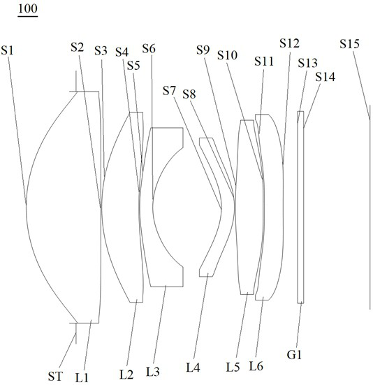
[0087] see figure 1 , which is a schematic diagram of the structure of the optical lens 100 provided in the first embodiment of the present invention, the optical lens 100 sequentially includes: a stop ST, a first lens L1, and a second lens L2 along the optical axis from the object side to the imaging surface S15 , the third lens L3, the fourth lens L4, the fifth lens L5, the sixth lens L6 and the filter G1.

[0088] Wherein, the first lens L1 has positive refractive power, the object side S1 of the first lens is a convex surface, and the image side S2 of the first lens is a concave surface at the near optical axis;

[0089] The second lens L2 has positive refractive power, the object side S3 of the second lens is a convex surface, and the image side S4 of the second lens is a concave surface at the near optical axis;

[0090] The third lens L3 has a negative refractive power, the object side S5 of the third lens is a convex surface, and the image side S6 of the third lens is...

no. 2 example

[0104] see Figure 5 , which is a schematic structural view of the optical lens 200 provided in the second embodiment of the present invention, the optical lens 200 of this embodiment is substantially the same as the first embodiment above, the main difference is that the image side S2 of the first lens is Convex, the object side S9 of the fifth lens is concave at the near optical axis, the fourth lens L4 has positive refractive power, and the radius of curvature, aspheric coefficient, thickness, and material of each lens surface are different.

[0105] Specifically, the design parameters of the optical lens 200 provided in this embodiment are shown in Table 3.

[0106] table 3

[0107]

[0108] The surface coefficients of each aspheric surface of the optical lens 200 in this embodiment are shown in Table 4.

[0109] Table 4

[0110]

[0111] Please refer to Figure 6 , Figure 7 and Figure 8 , showing the f-tanθ distortion curve, field curvature curve, and vertical...

no. 3 example

[0113] Such as Figure 9 As shown, it is a schematic structural diagram of the optical lens 300 provided in this embodiment. The optical lens 300 of this embodiment is substantially the same as the above-mentioned first embodiment, except that the fourth lens L4 has a positive refractive power, and the fifth lens L5 With negative refractive power, the sixth lens L6 has positive refractive power, the image side S10 of the fifth lens is concave at the near optical axis, the object side S11 of the sixth lens is convex at the near optical axis, and each lens surface type The radius of curvature, aspheric coefficient, thickness, and material are different.

[0114] Specifically, the design parameters of the optical lens 300 provided in this embodiment are shown in Table 5.

[0115] table 5

[0116]

[0117] Table 6 shows the surface coefficients of each aspheric surface of the optical lens 300 in this embodiment.

[0118] Table 6

[0119]

[0120] Please refer to Figure...


PUM


Abstract

The invention discloses an optical lens and imaging equipment. The optical lens sequentially comprises a diaphragm, a first lens, a second lens and a third lens from an object side to an imaging surface along an optical axis, the first lens has positive focal power, and the object side surface of the first lens is a convex surface; the object side surface of the second lens is a convex surface, and the image side surface of the second lens is a concave surface near the optical axis; the object side surface of the third lens is a convex surface, and the image side surface of the third lens is a concave surface; the fourth lens has focal power, and the object side surface of the fourth lens is a concave surface; the fifth lens has focal power; the sixth lens has focal power; wherein the first lens to the sixth lens at least comprise one aspheric lens. The optical lens has the advantages of long focal length, large aperture, short depth of field, high pixel and miniaturization.

Description

technical field [0001] The invention relates to the technical field of imaging lenses, in particular to an optical lens and imaging equipment. Background technique [0002] In recent years, with the rise of smartphones, the demand for differentiated shooting of flagship phones of major brands has increased day by day, and portrait lenses have also been born. Portrait lenses are generally telephoto lenses, and their unique long focal length and small viewing angle make them unique The shorter depth of field and larger magnification can effectively blur the background and highlight the focus of the subject, making the portrait more vivid, so people often call the telephoto lens a portrait lens. [0003] Generally, the Fno (aperture value) of a telephoto lens is about 3.0, and the leading Fno is 2.0. When shooting distant objects, because of its large depth of field, it often leads to the inability to clearly reflect the focus of the subject, and ultimately weakens the shooting...

Claims


Application Information

Patent Timeline
Patent Type & Authority Applications(China)
IPC IPC(8): G02B13/18
Inventor 章彬炜郑航鹏曾昊杰
Owner JIANGXI LIANYI OPTICS CO LTD
Why Eureka
Try Eureka