
Image sensor based on bidirectional time delay integration (TDI) and imaging method thereof

An image sensor, delay integration technology, applied in image communication, color TV parts, TV system parts and other directions, can solve the problem that one-way transfer cannot meet the needs of sweeping applications, affect the working life of the sensor, mechanical structure damage, etc. problem, to achieve the effect of small cost, low noise introduction level and low cost

Pending Publication Date: 2022-04-01
NANJING UNIV
View PDF6 Cites 0 Cited by
  • Summary
  • Abstract
  • Description
  • Claims
  • Application Information

AI Technical Summary

Problems solved by technology

[0004] However, in practical applications, one-way transfer cannot meet the requirements of sweeping applications, that is, only the data in one direction such as forward sweeping is valid during the sweeping process of the camera, so the interval between two valid data periods is longer
Using a mechanical rotation of 180 degrees can solve the reverse problem, but it is difficult and costly to realize high-speed mechanical control on satellites or aircraft, and high-repetition mechanical rotation is likely to cause damage to the mechanical structure and affect the overall working life of the sensor.

Method used


Image

  • Image sensor based on bidirectional time delay integration (TDI) and imaging method thereof
  • Image sensor based on bidirectional time delay integration (TDI) and imaging method thereof
  • Image sensor based on bidirectional time delay integration (TDI) and imaging method thereof

Examples


Embodiment Construction

[0057] The disclosure of the present invention will be described in detail below in conjunction with the accompanying drawings and specific embodiments. The specific embodiments described are only used to explain the principles of the disclosure of the present invention, and are not intended to limit the scope of the technical solutions disclosed in the present invention. It will be understood that, although the terms first and second etc. may be used herein to describe various elements, these elements should not be limited by these terms. These terms are only used to distinguish one element from another.

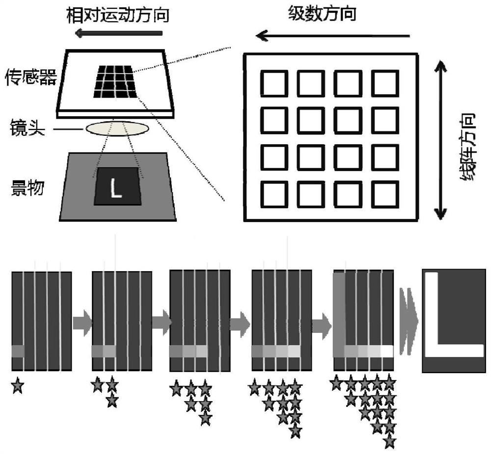
[0058] figure 1 It is a schematic diagram of imaging using a time-delayed integral image sensor based on a line scan system. Such as figure 1 As shown, when imaging based on a linear scanning system, the time-delay integral image sensor is composed of a linear array, where the series direction is the relative motion direction, that is, the scanning direction of the camera...


PUM


Abstract

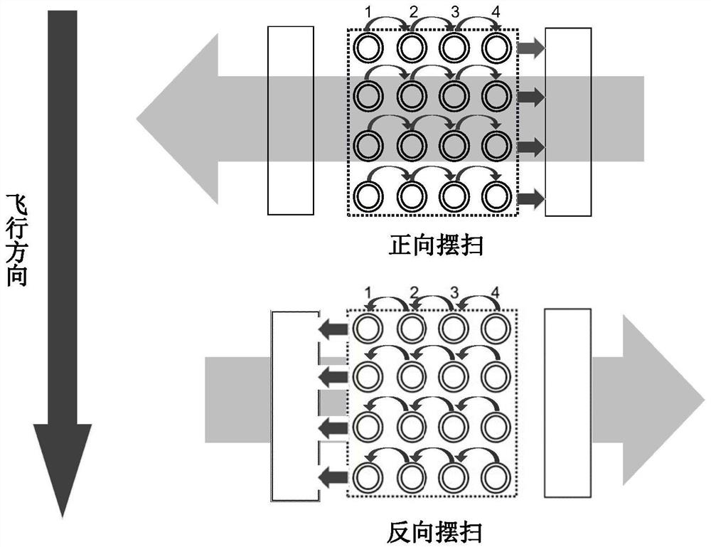
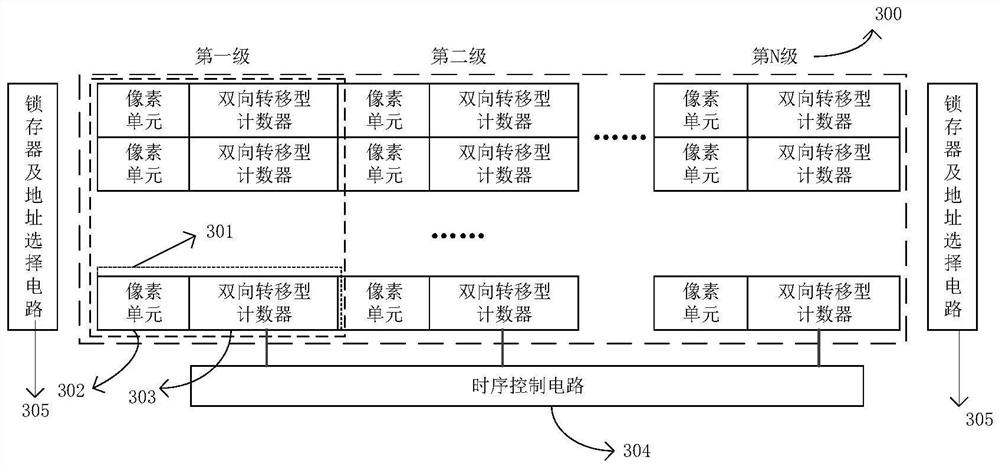
The invention discloses an image sensor based on bidirectional time delay integration (TDI) and an imaging method thereof. The image sensor comprises a multi-stage linear array which comprises a plurality of single-stage linear arrays arranged along the scanning direction of the image sensor; each stage of single-stage linear array enters a counting mode in response to a first control signal, enters a transfer mode in response to a second control signal, and enters a forward transfer or reverse transfer mode in response to a direction control signal in the transfer mode; in the counting mode, each level of single-level linear array counts optical signals on pixels; in the forward transfer mode, each stage of single-stage linear array stops counting, other stages of single-stage linear arrays except the last stage of single-stage linear array transfer the obtained count value to the next stage of single-stage linear array, and the last stage of single-stage linear array outputs the obtained count value; and in the reverse transfer mode, each stage of single-stage linear array stops counting, other stages of single-stage linear arrays except the first stage transfer the obtained count value to the previous stage, and the first stage outputs the obtained count value.

Description

technical field [0001] The disclosure of the present invention relates to an image sensor based on two-way time delay integration (Time delay integration, TDI) and its imaging method, in particular to an image sensor and corresponding imaging method. Background technique [0002] Time-delay integration is an imaging method to improve image signal-to-noise ratio in high-speed scanning imaging mode, which is usually used in CCD (charge coupled device) technology, that is, TDI-CCD image sensor. figure 1 A schematic diagram of a TDI image sensor used for imaging is shown. In the line scan system, the increasing direction of the TDI image sensor series is the camera scanning direction, multiple exposure imaging of the same scene through different levels of line arrays can prolong the equivalent integration time of imaging, which is conducive to improving the signal-to-noise ratio . There is a positive correlation between the signal-to-noise ratio and the number of stages of th...

Claims


Application Information

Patent Timeline
IPC IPC(8): H04N5/232H04N5/353H04N5/372
CPCY02D10/00
Inventor 毛成孙昕孔祥顺闫锋
Owner NANJING UNIV
Learn More