Large equipment turnover device
A technology for overturning devices and large-scale equipment, applied to workbenches, manufacturing tools, etc., can solve the problems of long overturning time, low efficiency, and difficulty in overturning large-scale equipment, and achieve the effect of safety in the overturning process
- Summary
- Abstract
- Description
- Claims
- Application Information
AI Technical Summary
Problems solved by technology
Method used
Image
Examples
Embodiment 1
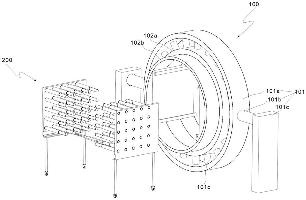
[0030] refer to figure 1 , image 3 and Figure 5 , is the first embodiment of the present invention. This embodiment provides a large-scale equipment overturning device. The large-scale equipment overturning device includes an overturning mechanism 100 and a clamping mechanism 200. The clamping mechanism 200 can clamp the large-scale equipment, and then the The overturning mechanism 100 performs overturning, which can safely complete overturning at any angle, and the overturning process is safe.
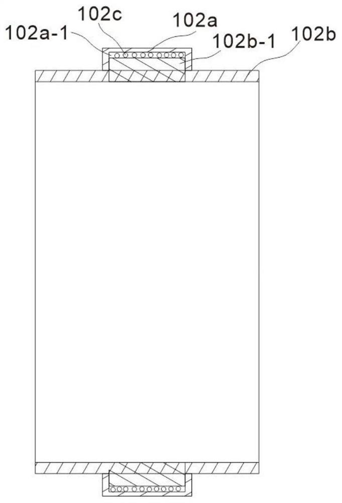
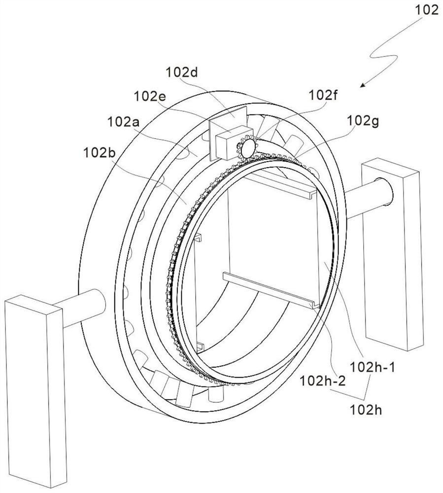
[0031] Specifically, the turning mechanism 100 includes a supporting component 101 and a turning component 102 matched with the supporting component 101 .
[0032] Preferably, the clamping mechanism 200 cooperates with the overturning assembly 102, including a clamping assembly 201, a shrinking assembly 202 arranged at the lower end of the clamping assembly 201, and a moving assembly 203 arranged at the bottom end of the shrinking assembly 202; Lifting, the clamping component 201...
Embodiment 2
[0040] refer to Figure 1-8 , is the second embodiment of the present invention, which is based on the previous embodiment.
[0041] Specifically, the clamping assembly 201 includes two symmetrically arranged pressure bearing plates 201a, the width of the two pressure bearing plates 201a is adapted to the limit frame 102h-2, and the opposite sides of the two pressure bearing plates 201a are evenly distributed with hollow Cylinder 201b, the upper and lower inner walls of the hollow cylinder 201b are provided with a limit groove 201b-1, the hollow cylinder 201b is slidingly provided with a clamping rod 201c, and the rod body of the clamping rod 201c is provided with a limit block 201c-1, the limit block 201c-1 is slidingly arranged in the limit groove 201b-1, the bottom end of the clamping rod 201c is provided with a spring 201c-2, and the middle part of the bottom end of the clamping rod 201c is provided with a first threaded rod 201c-3, and the spring 201c-2 Socketed on the o...
PUM
 Abstract
Description
Claims
Application Information
 - R&D
- Intellectual Property
- Life Sciences
- Materials
- Tech Scout
- Unparalleled Data Quality
- Higher Quality Content
- 60% Fewer Hallucinations
Browse by: Latest US Patents, China's latest patents, Technical Efficacy Thesaurus, Application Domain, Technology Topic, Popular Technical Reports.
© 2025 PatSnap. All rights reserved.Legal|Privacy policy|Modern Slavery Act Transparency Statement|Sitemap|About US| Contact US: help@patsnap.com


