Thermal retroflex energy-saving printer

A printer and winding technology, applied in printing devices, printing and other directions, can solve problems such as severe bending and wrinkling of paper, motor heat transfer processing, adverse effects on head performance and life, and achieve the effect of improving printing quality.

Pending Publication Date: 2022-04-05
XIAMEN RONGTA TECH
15 Cites 0 Cited by

AI-Extracted Technical Summary

Problems solved by technology

[0004] First, the paper used is rolled into a paper roll and placed in the paper bin for printing. Therefore, the entire paper is bent after the thermal printer prints out, especially the smaller the paper roll, the more the paper is bent and wrinkled or pri...

Method used

In summary, the energy-saving printer of the present invention realizes the thermal shaping of the paper by setting the rewinding curved portion opposite to the winding direction of the paper roll, and cooperating with the heating device for heating the paper. , making the curved paper more flat and improving the printing quality; and by heating the paper, it can effectively prevent the printer from printing light and fuzzy, and the printing quality drops sharply when the ambient temperature is too low in winter.
Please refer to Fig. 1 to 6, it is a kind of thermal rewinding energy-saving printer as the best embodiment of the present invention, comprises printer main body, is provided with the paper storehouse 10 that is used to place paper roll and is used for paper in the printer main body The moving paper path 20; the paper path 20 is near the paper bin 10 with a rewinding curve 21 that is opposite to the winding direction of the paper roll, that is, the winding direction of the paper is in an "S" shape, and then passes through the printing rubber roller 30 and The channel between the thermal print heads realizes paper output tending to be flat; the printer body is equipped with a heating device for heating the paper in the rewinding curved part 21; through the heating of the rewinding curved part 21, the paper is Thermal shaping, avoid springback, make the bent paper more flat and improve printing quality.
Two supporting columns 631 for inserting the rotating shaft 64 into the groove 721 are set on the fixed cover 63, and the two ends of the rotating shaft 64 are rotationally ...

Abstract

The invention provides a thermal retroflex energy-saving printer which comprises a printer body, and a paper bin used for containing paper rolls and a paper feeding channel used for moving paper are arranged in the printer body. A back-winding curved part opposite to the winding direction of the paper roll is arranged at the position, close to the paper bin, of the paper feeding channel; a heating device used for heating paper in the reverse-winding curved part is arranged in the printer main body; according to the energy-saving printer disclosed by the invention, the back-winding curved part opposite to the winding direction of the paper roll is arranged and is matched with the heating device for heating the paper, and the back-winding curved part is matched with heating, so that thermal shaping of the paper is realized, the bent paper is smoother, and the printing quality is improved.

Application Domain

Technology Topic

Image

  • Thermal retroflex energy-saving printer
  • Thermal retroflex energy-saving printer
  • Thermal retroflex energy-saving printer

Examples

  • Experimental program(1)

Example Embodiment

[0030] In order to make the technical problems, technical solutions and beneficial effects to be solved by the present invention clearer and more comprehensible, the present invention will be further described in detail below with reference to the accompanying drawings and embodiments. It should be understood that the specific embodiments described herein are only used to explain the present invention, but not to limit the present invention.
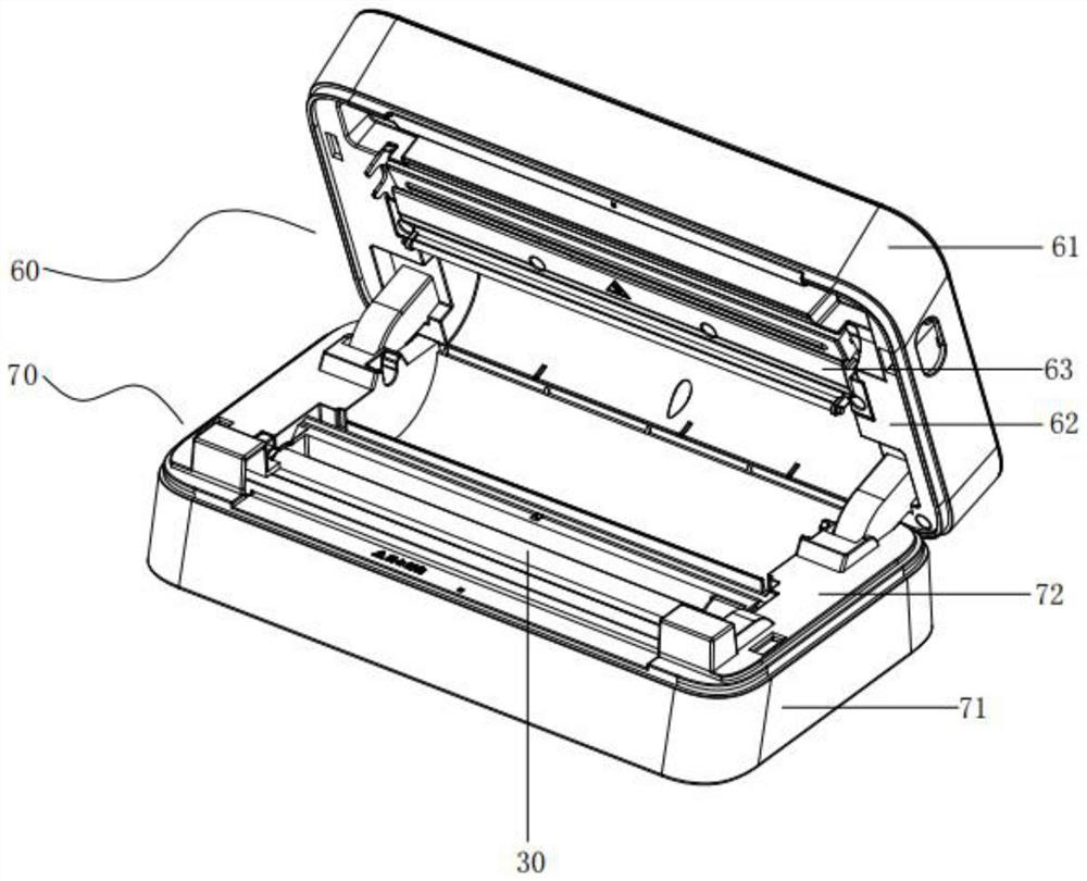
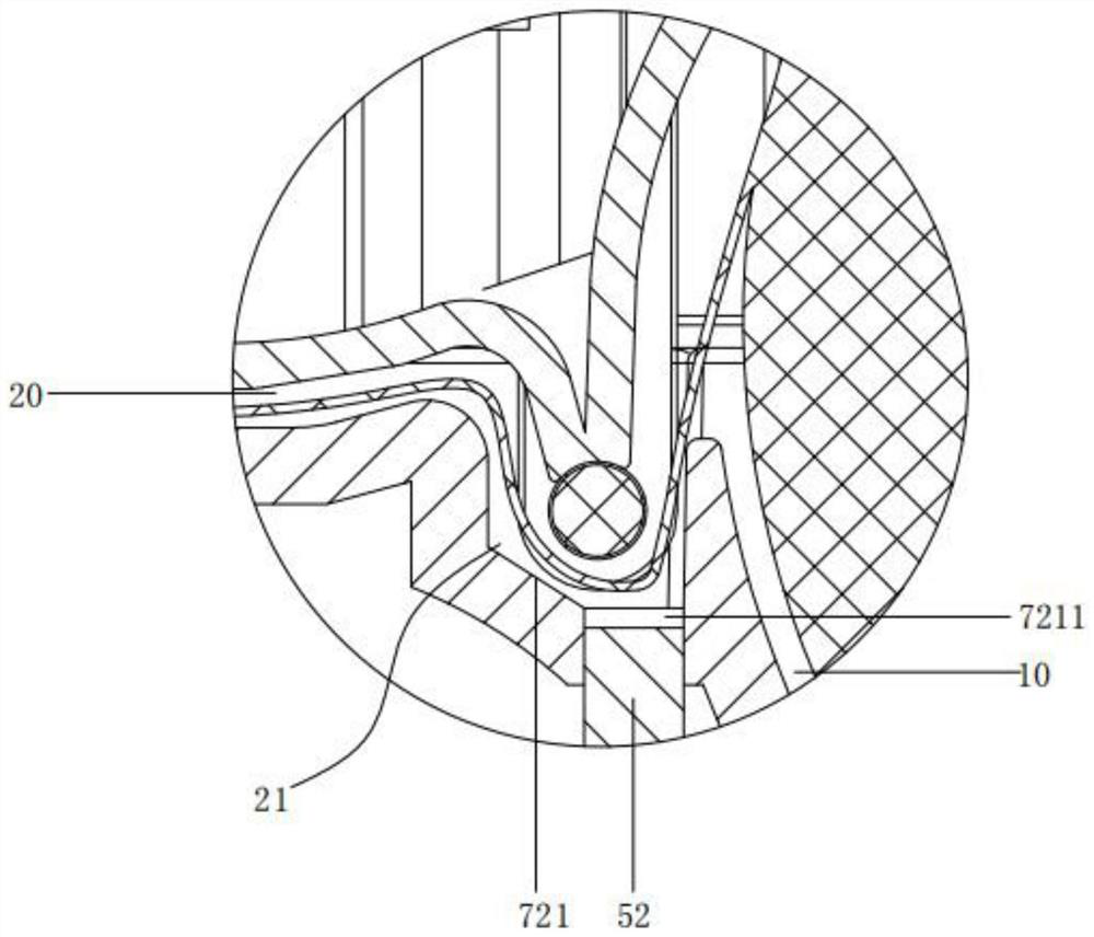
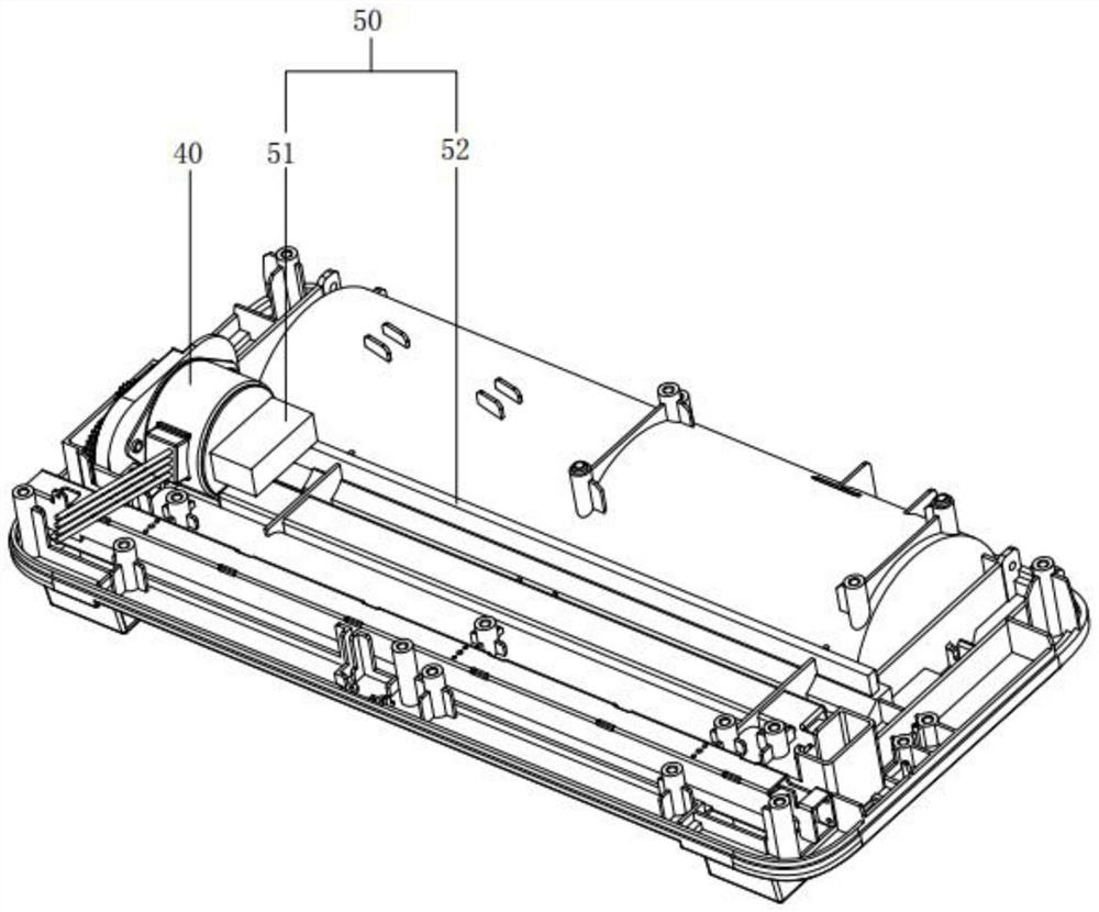
[0031] see Figures 1 to 6 , is a thermal rewinding energy-saving printer as a preferred embodiment of the present invention, comprising a printer body, a paper bin 10 for placing paper rolls and a paper feeding channel 20 for paper movement in the printer body; paper feeding; The channel 20 is provided with a reverse winding portion 21 opposite to the wrapping direction of the paper roll near the paper magazine 10, that is, the wrapping direction of the paper is first in an "S" shape, and then passes through the channel between the printing rubber roller 30 and the thermal print head, Realize the paper output tends to be flat; a heating device for heating the paper in the rewinding curved part 21 is arranged in the main body of the printer; the rewinding curved part 21 cooperates with heating to realize the thermal shaping of the paper, avoiding springback and making the bending The paper is more flat and the printing quality is improved.
[0032] The printer body is provided with a printing rubber roller 30 and a motor 40 for driving the printing rubber roller 30 to rotate. The heating device adopts a heat recovery block 50 which is in contact with the outer surface of the motor 40 and is used for recovering the heat energy generated by the motor 40, and the heat energy collected by the heat recovery block 50 is used to heat the paper. The heat recovery block 50 includes a recovery part 51 attached to the outer surface of the motor 40 , and a heating part 52 connected to the recovery part 51 and used for heating the paper. The use of the motor 40 to generate heat energy cooperates with the rewinding part 21 to realize the rewinding function, and realizes the shaping function of the paper; therefore, by transferring the harmful heat energy of the excess motor 40 and recycling it for the second time, the service life of the provided product can be improved and the performance can be improved. It is greatly improved, and the advantages of energy saving, environmental protection and waste reduction are achieved.
[0033] The main body of the printer includes an upper assembly 60 and a lower assembly 70 which are rotatably connected on one side. The upper assembly 60 and the lower assembly 70 form a paper bin 10 and a paper feeding channel 20 . The upper assembly 60 is also provided with a rotating shaft 64 for changing the direction of the paper, and the lower assembly 70 is provided with a groove 721 for the rotating shaft 64 to be embedded, and a rewinding curved portion 21 is formed between the rotating shaft 64 and the groove 721 . The bottom of the groove 721 is provided with a long hole 7211 for the heat recovery block 50 to pass through; specifically, the heating block enters the groove 721 through the long hole 7211 to heat the paper.
[0034] The upper assembly 60 includes an upper casing 61 and an upper bracket 62 arranged inside the upper casing 61 , the lower assembly 70 includes a lower assembly 70 whose lower casing 71 has been arranged inside the lower casing 71 , and the printing rubber roller 30 and the motor 40 are arranged On the lower bracket 72, and the motor 40 is located between the lower casing 71 and the lower bracket 72, the upper assembly 60 is also disposed on the upper bracket 62 and is used to limit the thermal print head. The fixed cover 63, the rotating shaft 64 and the fixed cover 63 / The upper bracket 62 is rotatably connected, and the groove 721 is arranged on the lower bracket 72 .
[0035] The fixed cover 63 is provided with two support columns 631 for inserting the rotating shaft 64 into the groove 721, and both ends of the rotating shaft 64 are rotatably connected to the supporting columns 631; By means of transition fit, in the process of paper feeding, the rotating shaft 64 can also be rotated to make the paper feeding more smoothly; the two ends of the rotating shaft 64 are provided with C-shaped buckles 65 that restrict it to the two support columns 631; specifically, The C-shaped buckles 65 are located outside the two support columns 631 , and the rotating shaft 64 is provided with an annular groove for matching with the C-shaped buckles 65 .
[0036] Since the diameter of the rotating shaft 64 is selected to be small in order to realize that the external dimensions of the thermal printer do not change, in order to avoid bending during the rotation, the fixed cover 63 and located between the two supporting columns 631 are provided with a bearing for bearing against the rotating shaft 64. The support part 632; the support part 632 is provided with an arc-shaped groove 6321 which is matched with the outer surface of the rotating shaft 64.
[0037] To sum up, the energy-saving printer of the present invention realizes thermal shaping of the paper by setting the rewinding curved part opposite to the wrapping direction of the paper roll, and cooperates with the heating device for heating the paper, and the rewinding curved part cooperates with heating to realize the thermal shaping of the paper, so that the bending The paper is more flat and the printing quality is improved; and by heating the paper, the printer can effectively prevent the printer from printing light and blurry, and the printing quality drops sharply when the ambient temperature is too low in winter.
[0038] The present invention has been exemplarily described above in conjunction with the accompanying drawings. Obviously, the specific implementation of the present invention is not limited by the above methods, as long as various insubstantial improvements made by the method concept and technical solutions of the present invention are adopted, or no improvement is made. It is within the protection scope of the present invention to directly apply the concepts and technical solutions of the present invention to other occasions.

PUM

no PUM

Description & Claims & Application Information

We can also present the details of the Description, Claims and Application information to help users get a comprehensive understanding of the technical details of the patent, such as background art, summary of invention, brief description of drawings, description of embodiments, and other original content. On the other hand, users can also determine the specific scope of protection of the technology through the list of claims; as well as understand the changes in the life cycle of the technology with the presentation of the patent timeline. Login to view more.

Similar technology patents

Classification and recommendation of technical efficacy words

Why Eureka
Try Eureka