

Device and method for controlling ink jet printing time
A technology of inkjet printing and control method, which is applied in the direction of printing, etc., and can solve the problems of limited printer body size and limited reduction in the length of the 10 strokes of the inkjet head, and achieve the effect of improving printing quality and increasing the printable area
- Summary
- Abstract
- Description
- Claims
- Application Information
AI Technical Summary
Problems solved by technology
Method used
Image

Examples
Embodiment Construction
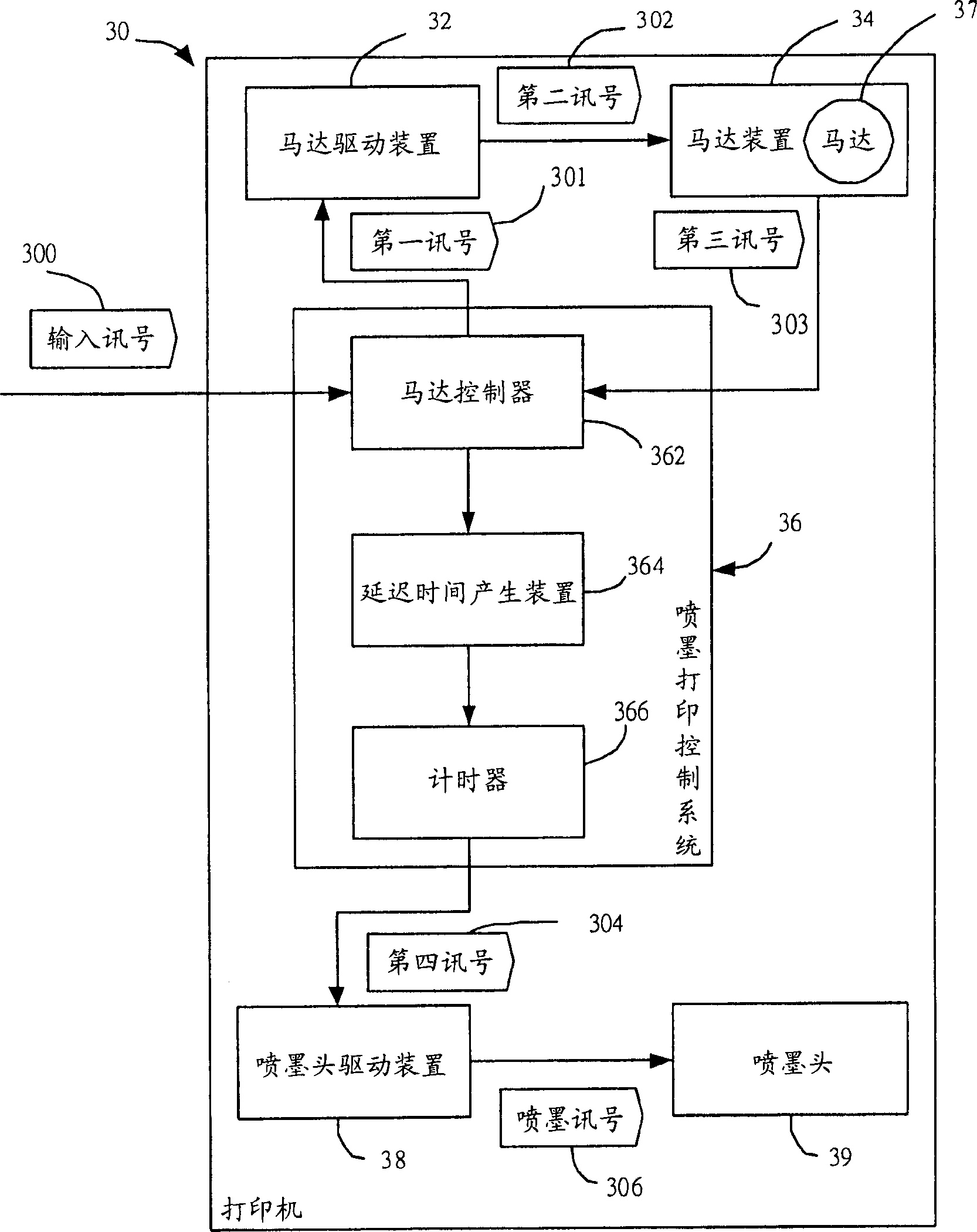
[0041] see image 3 , image 3 It is a system block diagram of the printer 30 applying the inkjet printing control system 36 of the present invention. In one embodiment, the inkjet printing control system 36 of the present invention is applied to a printer 30 , and the inkjet printing control system 36 is used to control an inkjet head 39 . The printer 30 includes a motor driving device 32 , a motor device 34 , an inkjet printing control system 36 , an inkjet head driving device 38 , and an inkjet head 39 . The motor device 34 includes a motor 37 and an encoder (not shown). The motor 37 is a DC motor. The motor driving device 32 outputs a second signal 302 to the motor device 34 according to a first signal 301 . The motor 37 of the motor device 34 receives the second signal 302 to correspondingly drive the inkjet head 39 to move, and the encoder of the motor device 34 outputs a third signal 303 to the inkjet printing control system 36 according to the moving position of th...
PUM
 Abstract
Description
Claims
Application Information