

Drawing machine
A photo machine and frame technology, applied in printing, winding strips, thin material processing, etc., can solve the problems of wrinkles, small adsorption area, etc., achieve the effect of increasing the adsorption area and improving printing quality
- Summary
- Abstract
- Description
- Claims
- Application Information
AI Technical Summary
Problems solved by technology
Method used
Image

Examples
Embodiment 1
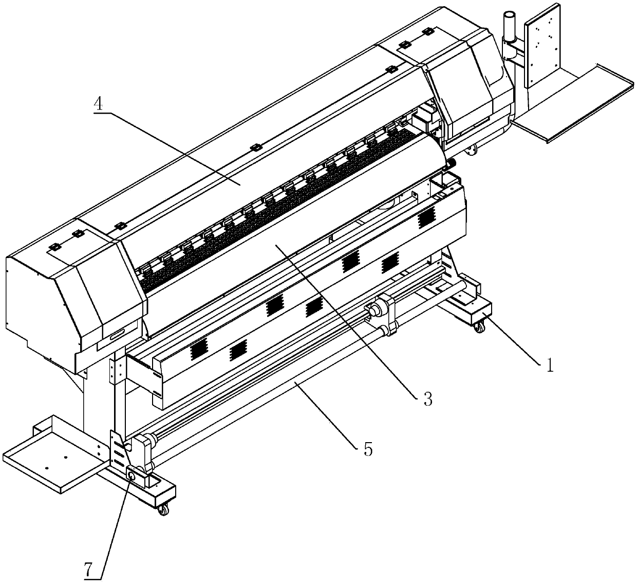
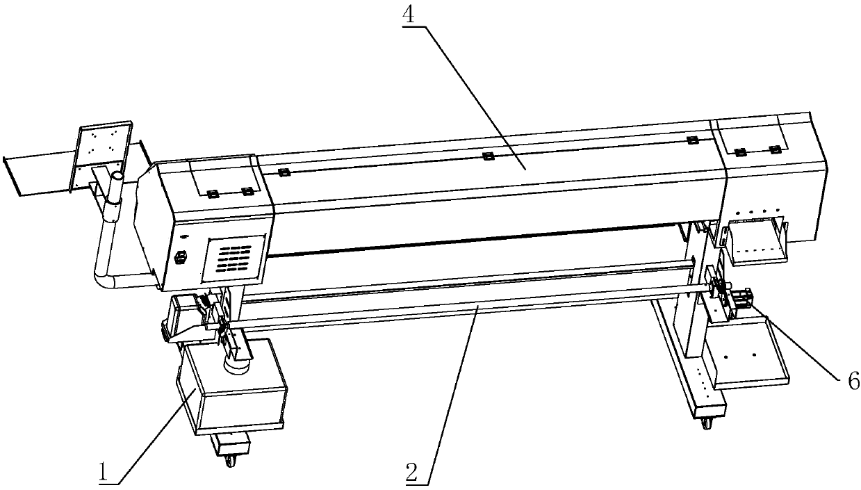
[0042] Such as figure 1 and figure 2 Shown, a kind of photo machine, comprises frame 1, is used for unwinding roller 2 of unwinding, is used to place the printing platform 3 of the printing medium that is discharged by unwinding roller 2, is used for printing printing assembly 4 and is used for The winding roller 5 of receiving material. One end of the unwinding roller 2 is provided with a first driving motor 6 for driving the unwinding roller 2 to rotate, and the first driving motor 6 is fixedly installed on the frame 1 . One side of the winding roller 5 is provided with a second driving motor 7 for driving the winding roller 5 to rotate, and the second driving motor 7 is fixedly installed on the frame 1 . The unwinding roller 2 unwinds the printing medium, and the printing medium is smoothly transported through the printing platform 3 , and is printed by the printing component 4 when passing the printing platform 3 , and then wound up on the winding roller 5 .
[0043] S...
Embodiment 2
[0049] The difference between Embodiment 2 and Embodiment 1 is that, as Figure 6 As shown, in order to enable the printing medium to be transported more smoothly, both the winding roller 5 and the unwinding roller are located on the same side of the frame 1 , and the unwinding roller 2 is located above the winding roller 5 . The frame 1 is provided with a guide mechanism 26 for guiding the direction of printing materials. The guiding mechanism 26 is located on one side of the winding roller 5 . The guiding mechanism 26 includes a connecting plate 27 rotatably connected to the frame 1 and a guiding roller 28 parallel to the winding roller 5 . Two connecting plates 27 are provided and are respectively located at two ends of the guide roller 28 , and the guiding roller 28 is rotatably connected to the connecting plate 27 . There are three guide rollers 28 arranged in a triangular shape. The printing medium goes around three guide rollers 28 in turn and is wound up on the wind...
Embodiment 3
[0063] The difference between Embodiment 3 and Embodiment 1 is that, as Figure 8 As shown, in order to enable the printing medium to be transported more smoothly, both the winding roller 5 and the unwinding roller 2 are located on the same side of the frame 1 , and the unwinding roller 2 is located above the winding roller 5 . The frame 1 is provided with a tensioning mechanism 38 for tensioning the direction of the material. The tensioning mechanism 38 is located on one side of the winding roller 5 . Such as Figure 9 As shown, the tensioning mechanism 38 includes a first mounting plate 39 installed on both sides of the winding roller 5, a mounting groove 40 opened in the vertical direction on the side of the first mounting plate 39 facing the winding roller 5, and both ends are embedded. The tension roller 41 is arranged in the installation groove 40 . The inner wall of the installation groove 40 is provided with a rack 42 along the vertical direction, and the two ends o...
PUM
 Abstract
Description
Claims
Application Information