
Transformer door lock

A technology for transformers and door locks, applied in the field of transformers, can solve the problems of inconvenient use and the lack of a self-locking structure for the motor, and achieve the effects of convenient use, increased operation modes, and realization of steering operation.

Active Publication Date: 2022-04-05
河北大唐国际丰宁风电有限责任公司
View PDF10 Cites 0 Cited by
  • Summary
  • Abstract
  • Description
  • Claims
  • Application Information

AI Technical Summary

Problems solved by technology

[0004] However, because most of the commonly used motors do not have a self-locking structure, they are mostly driven by power-on during use. Once the device is powered off during use, the maintenance personnel cannot open the cabinet door and can only destroy the cabinet door. inconvenient

Method used


Image

  • Transformer door lock
  • Transformer door lock
  • Transformer door lock

Examples


Embodiment Construction

[0023] In order to make the technical problems, technical solutions and beneficial effects to be solved by the present invention clearer, the present invention will be further described in detail below in conjunction with the accompanying drawings and embodiments. It should be understood that the specific embodiments described here are only used to explain the present invention, not to limit the present invention.

[0024] The transformer door lock provided by the present invention is now described.

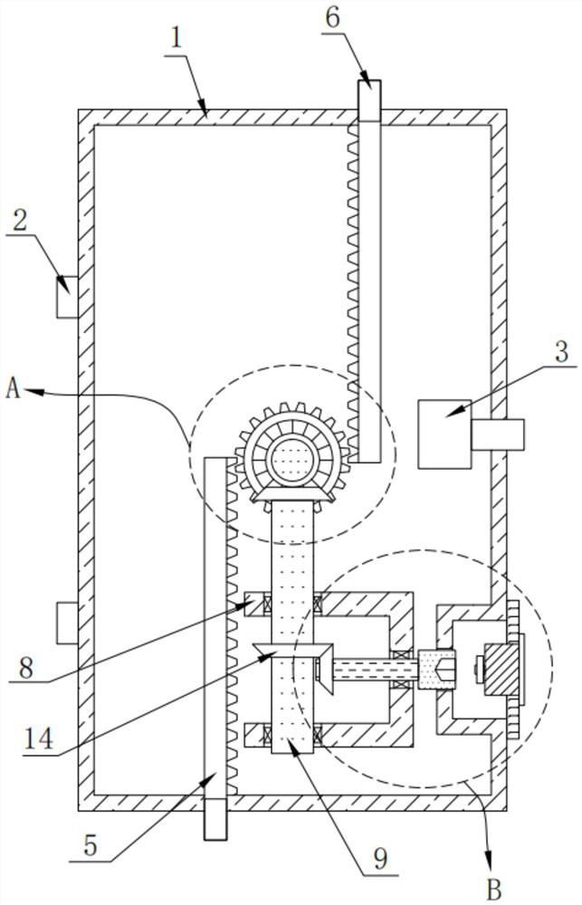
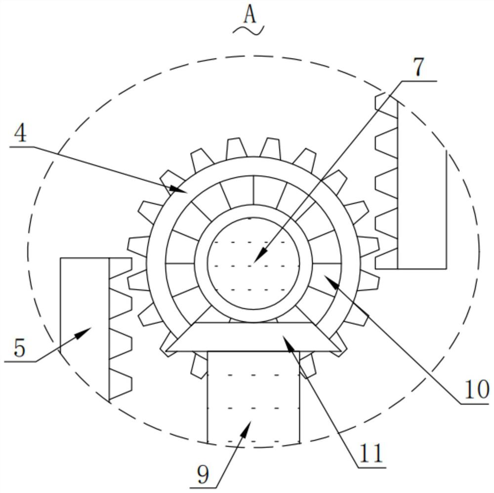
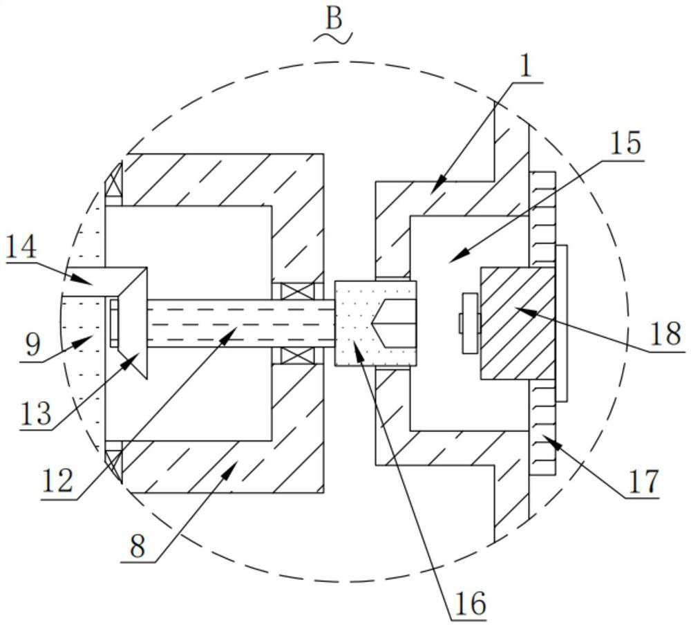
[0025] Please also refer to Figure 1 to Figure 3 , The transformer door lock provided by the first embodiment of the present invention includes a door body 1 , a hinge 2 , a spur gear 4 , a rack 5 , a lock tongue 6 and an adapter post 7 . The hinge 2 is arranged on one side of the door body 1, a cavity is provided inside the door body 1, and a cylindrical gear 4 is arranged in the middle of the cavity, the axis of the cylindrical gear 4 is perpendicular to the door body, and th...


PUM


Abstract

The invention provides a transformer door lock which comprises a door lock body composed of a door body, a hinge, an electronic lock, a cylindrical gear, a rack, a spring bolt and a rotary matching column, the cylindrical gear is fixedly arranged on the rotary matching column in a sleeving mode, a mounting support is fixedly arranged in the door body and located below the rotary matching column, and the hinge is fixedly arranged on the door body. The mounting support and the two racks are arranged in an avoiding mode, a middle rotating shaft is arranged on the mounting support in a rotating mode, the middle rotating shaft is longitudinally arranged and is perpendicular to the rotating matching column, a first bevel gear is fixedly arranged at the top end of the middle rotating shaft, and the rotating matching column is fixedly sleeved with a second bevel gear meshed with the first bevel gear. The transformer door lock provided by the invention has the advantages that manual unlocking can be carried out under the condition that equipment is powered off, the operation modes are increased, and a user can conveniently use the transformer door lock.

Description

technical field [0001] The invention belongs to the technical field of transformers, and more specifically relates to a transformer door lock. Background technique [0002] In recent years, the phenomenon of theft and destruction of power facilities has spread across the country, and the damage to the power grid has become more and more serious, especially the theft of power transformers is the most serious, which directly or indirectly causes economic losses and seriously affects the operation and safety of the power grid. The theft of transformers has caused great harm to the normal production of cities, counties, villages and towns along the line. The security of the power grid has become a sharp sword hanging over the heads of power companies; the supply of power, especially the safe, stable and reliable supply of power, It is directly related to the development of the national economy and the vital interests of the people, but only a mechanical lock or an electronic loc...

Claims


Application Information

Patent Timeline
Patent Type & Authority Applications(China)
IPC IPC(8): E05C9/04E05C9/12E05B65/52
CPCY02E10/50
Inventor 王蒙刘春雷于润权李冰石朝卫宋梦阳蔡国鹏杨晶鑫
Owner 河北大唐国际丰宁风电有限责任公司
Learn More