Adjustable battery pack
A battery pack and adjustable technology, applied to battery pack components, circuits, electrical components, etc., can solve the problem of limited rectangular shape of the battery pack, inability to make full use of the inner space of the arc-shaped housing, and inability to increase the capacity of the battery pack, etc. problem, to achieve the effect of increasing the capacity
- Summary
- Abstract
- Description
- Claims
- Application Information
AI Technical Summary
Problems solved by technology
Method used
Image
Examples
Embodiment 1
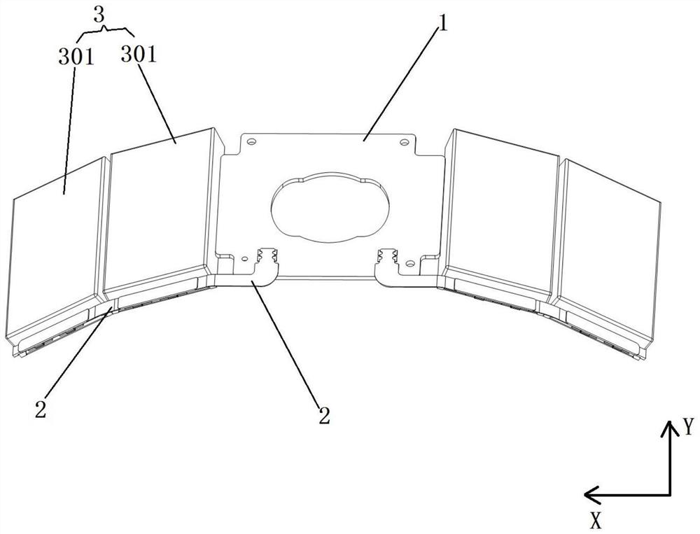
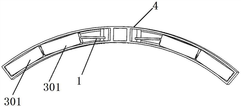
[0049] like figure 1 and figure 2 As shown, in this embodiment, the two adjacent battery cells 301 in each battery unit 3 are arranged back and forth along the X-axis direction of the protection board 1, and the two adjacent battery cells 301 are located in the same The two sides of the side are connected by the flexible connector 2 .
[0050] Specifically, two adjacent cells 301 can be divided into a first cell and a second cell, wherein the two width sides of the first cell and the second cell located on the same side are arranged one after the other, and the flexible connection Component 2 connects the two width sides of the first cell and the second cell on the same side, so that two adjacent cells 301 are connected, and the one cell 301 closest to the protection board 1 is connected by a flexible connector 2 Connect with the protection board 1.
[0051] Through the above design, the unused space inside the arc-shaped casing of the existing electronic device can be re...
Embodiment 2
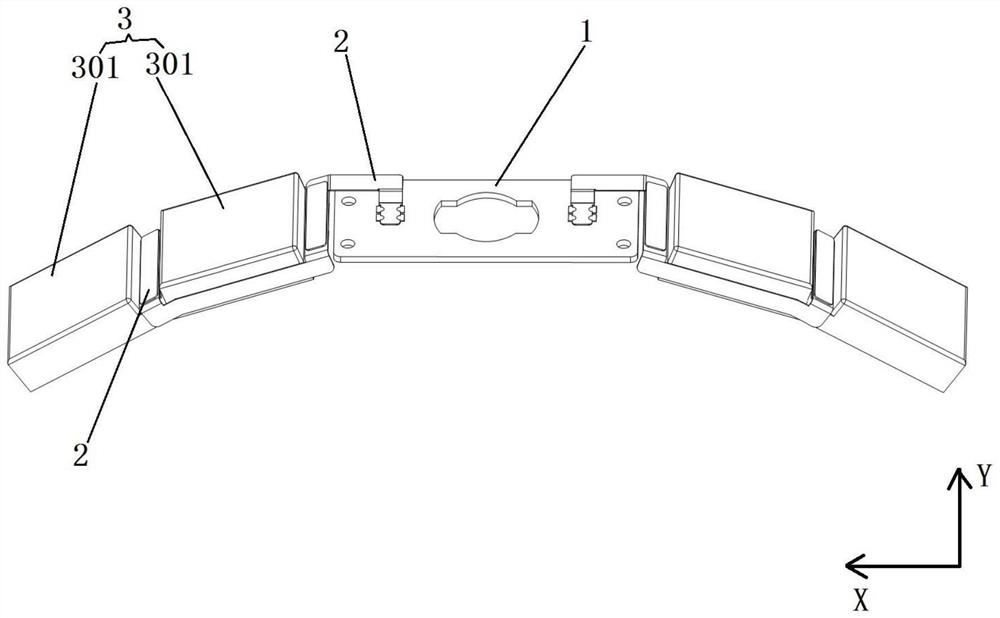
[0053] like image 3 and Figure 4As shown, in this embodiment, the adjacent two battery cells 301 in each battery unit 3 are arranged back and forth along the X-axis direction of the protection plate 1, and the adjacent two battery cells 301 pass through the The flexible connectors 2 are connected end to end.
[0054] Specifically, the two adjacent cells 301 can be divided into a first cell and a second cell, wherein the first cell and the second cell are connected end to end through the flexible connector 2 , that is, the first cell and the second cell The front and rear opposite sides of the cell are connected by the flexible connector 2 , and a cell 301 closest to the protection board 1 is connected with the protection board 1 through the flexible connector 2 .
[0055] Through the above-mentioned design, the battery pack can be applied to the case where the width of the arc-shaped casing of the electronic device is small, so that the arc-shaped casing of the electronic ...
Embodiment 3
[0057] like Figure 5 and Image 6 As shown, in this embodiment, two adjacent cells 301 in each battery unit 3 are arranged side by side along the Y-axis direction of the protection plate 1, and two adjacent two cells 301 are arranged opposite to each other. The sides are connected by the flexible connector 2 .
[0058] Specifically, the two adjacent cells 301 may be a first cell and a second cell, wherein the first cell and the second cell are arranged side by side along the Y-axis direction of the protection board 1 , that is, left and right side by side. Left and right opposite sides of a cell and a second cell are connected by flexible connectors 2 , and the first and second cells are connected to the protection board 1 through the flexible connectors 2 .
[0059] Through the above design, the battery pack can be applied to the three-dimensional arc-shaped casing of the electronic device, and the arc-shaped casing of the electronic device can be fully utilized, thereby e...
PUM
 Abstract
Description
Claims
Application Information
 - R&D
- Intellectual Property
- Life Sciences
- Materials
- Tech Scout
- Unparalleled Data Quality
- Higher Quality Content
- 60% Fewer Hallucinations
Browse by: Latest US Patents, China's latest patents, Technical Efficacy Thesaurus, Application Domain, Technology Topic, Popular Technical Reports.
© 2025 PatSnap. All rights reserved.Legal|Privacy policy|Modern Slavery Act Transparency Statement|Sitemap|About US| Contact US: help@patsnap.com


