
Speed limiting wheel disc mechanism based on disc brake

A speed-limiting wheel and disc brake technology, which is applied in the field of non-motor vehicle speed-limiting mechanisms, can solve the problems of secondary injury of drivers and passengers, poor protection performance of drivers and passengers, and weak safety awareness, and achieves controllability and safety. High, improve the effect of stability and reliability

Inactive Publication Date: 2022-04-08
文忠忠
View PDF0 Cites 0 Cited by
  • Summary
  • Abstract
  • Description
  • Claims
  • Application Information

AI Technical Summary

Problems solved by technology

[0002] As a reliable braking mechanism, disc brakes have been widely used in various non-motor vehicles with the development of manufacturing technology. However, the drivers of non-motor vehicles are not as professionally trained as car drivers. The grasp of speed and braking distance is mostly based on their own experience, and their safety awareness in the driving process is relatively weak, and it is difficult to effectively control the speed of the vehicle according to the actual situation, so that it is often caused by speed in the process of driving. Accidents occur due to excessive speed, and compared with automobiles, non-motorized vehicles have poor protection performance for drivers and passengers. secondary injury

Method used


Image

  • Speed limiting wheel disc mechanism based on disc brake
  • Speed limiting wheel disc mechanism based on disc brake
  • Speed limiting wheel disc mechanism based on disc brake

Examples


Embodiment Construction

[0020] The following will clearly and completely describe the technical solutions in the embodiments of the present invention with reference to the accompanying drawings in the embodiments of the present invention. Obviously, the described embodiments are only some, not all, embodiments of the present invention. Based on the embodiments of the present invention, all other embodiments obtained by persons of ordinary skill in the art without making creative efforts belong to the protection scope of the present invention.

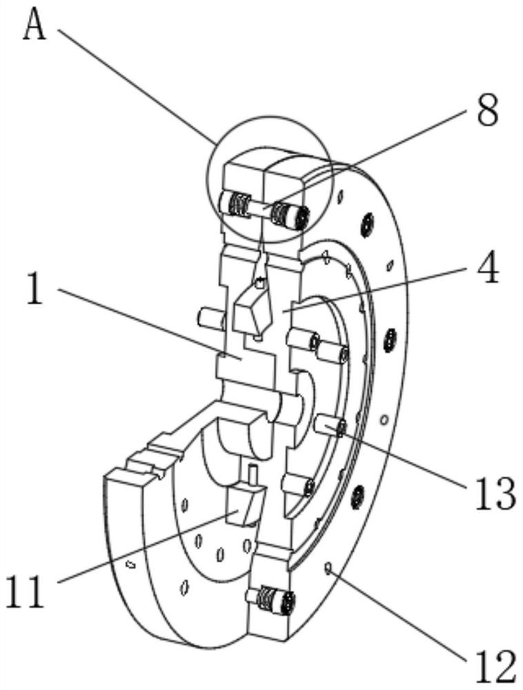
[0021] see figure 1 , a speed-limiting wheel mechanism based on disc brakes, including a first brake disc 1, a second brake disc 4 and a connecting mechanism 8, and the first brake disc 1 and the connecting mechanism 8 are fixed by the connecting mechanism 8 connection, such as figure 2 As shown, one side of the first brake disc 1 is provided with an arc-shaped groove I2, and a limit post 3 is fixedly installed in the middle of one side of the first brake di...


PUM


Abstract

The invention relates to the technical field of non-motor vehicle speed limiting mechanisms, and discloses a speed limiting wheel disc mechanism based on a disc brake, the speed limiting wheel disc mechanism comprises a first brake disc, a second brake disc and a connecting mechanism, the first brake disc and the connecting mechanism are fixedly connected through the connecting mechanism, one side of the first brake disc is provided with an arc-shaped groove I, and the other side of the first brake disc is provided with an arc-shaped groove II; a limiting supporting column is fixedly installed in the middle of one side of the first brake disc, and an arc-shaped groove II is formed in the side, corresponding to the arc-shaped groove I in the first brake disc, of the second brake disc. According to the speed limiting wheel disc mechanism based on the disc brake, the maximum compression displacement of a single set of reset springs is set, so that it is ensured that centrifugal force borne by a transmission pressing block after a non-motor vehicle reaches the set speed can effectively overcome the elastic force influence of the reset springs; and the displacement amount for extruding the first brake disc and the second brake disc to move towards the two sides can be in contact with calipers on the disc brake, and the braking effect is achieved.

Description

technical field [0001] The invention relates to the technical field of speed-limiting mechanisms for non-motor vehicles, in particular to a speed-limiting wheel mechanism based on disc brakes. Background technique [0002] As a reliable braking mechanism, disc brakes have been widely used in various non-motor vehicles with the development of manufacturing technology. However, the drivers of non-motor vehicles are not as professionally trained as car drivers. The grasp of speed and braking distance is mostly based on their own experience, and their safety awareness in the driving process is relatively weak, and it is difficult to effectively control the speed of the vehicle according to the actual situation, so that it is often caused by speed in the process of driving. Accidents occur due to excessive speed, and compared with automobiles, non-motorized vehicles have poor protection performance for drivers and passengers. injury. [0003] Therefore, in order to ensure the s...

Claims


Application Information

Patent Timeline
IPC IPC(8): F16D65/092F16D65/847F16D65/12
Inventor 文忠忠
Owner 文忠忠
Learn More