Electric heating flow divider

A technology of electric heating and shunt, applied in the field of low pressure casting, can solve the problem of high cost, and achieve the effect of saving riser pipes, saving costs, improving safety and controllability

Inactive Publication Date: 2016-11-23
WUXI LIHU PRESSURIZE TECH CO LTD
View PDF9 Cites 1 Cited by
  • Summary
  • Abstract
  • Description
  • Claims
  • Application Information

AI Technical Summary

Problems solved by technology

[0002] In low-pressure casting equipment, the riser pipe is a commonly used consumable part, which is the bulk of the product cost; when using the bottom injection form, a riser pipe can only supply one cavity and cast one product at a time; such as a mold There are multiple mold cavities, each cavity has a liquid inlet, and each liquid inlet has to be equipped with a liter of liquid pipe, which is costly

Method used


Image

  • Electric heating flow divider

Examples


Embodiment Construction

[0012] The specific implementation manners in this application will be further described below in conjunction with the accompanying drawings.

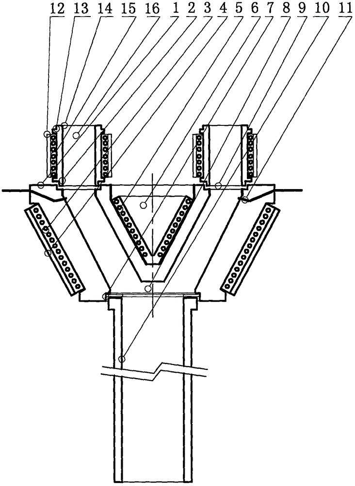
[0013] figure 1 Including shunt body 1, shunt pipe groove 2, electric heating jacket 3, heat preservation jacket 4, electric heating core 5, vacuum insulation cone 6, riser pipe matching groove 7, main flow channel 8, shunt flow passage 9, riser pipe 10 , Liquid level contact 11, heat preservation ring 12, shunt pipe 13, shunt slot 14, spring heating ring 15, shunt hole 16, etc.

[0014] like figure 1 As shown, the application is an electric heating shunt, including a fluid diversion mechanism, a shunt cavity mechanism, and a heating and heat preservation mechanism;

[0015] The fluid-distributing mechanism includes a fluid-distributing body 1, a liquid riser matching groove 7, a distribution pipe groove 2, a thermal insulation ring 12, a shunt pipe 13, a shunt opening groove 14, a spring heating ring 15, and a shunt hole 16; The gr...


PUM


Abstract

The invention discloses an electric heating flow divider. The electric heating flow divider is characterized by comprising a flow division body mechanism, a flow division cavity mechanism and a heating and heat insulating mechanism; the flow division body mechanism is provided with a flow division body, a liquid rising pipe matching groove is formed in the lower end face of the flow division body, and the upper end face of the flow division body is provided with flow division pipe grooves and flow division pipes; the flow division cavity mechanism is arranged in the flow division body and comprises a main runner arranged in the liquid rising pipe matching groove, branch runners arranged in die matching grooves, and the lower ends of the branch runners communicate with the upper end of the main runner; and a liquid level contact is arranged in an upper opening of each branch runner; and the heating and heat insulating mechanism comprises electric heating sleeves arranged on the outer walls of the flow division body, and heat insulating sleeves are arranged on the outer walls of the electric heating sleeves; an electric heating core is arranged in the center of the flow division body; and a vacuum heat insulating cone is arranged in the center of the electric heating core. The electric heating sleeves, the electric heating core and spring heating rings are used for heating the flow division body and the flow division pipes, so that the technical requirement of molten aluminum in the flow divider is met; and safety and controllability of low-pressure casting are improved, and cost is saved.

Description

technical field [0001] This application relates to low pressure casting, in particular to an electrically heated shunt. Background technique [0002] In low-pressure casting equipment, the riser pipe is a commonly used consumable part, which is the bulk of the product cost; when the bottom injection form is used, a riser pipe can only supply one cavity and cast one product at a time; such as a mold There are multiple mold cavities on the top, and there is a liquid inlet under each cavity mold, and each liquid inlet has to be prepared with a liter of liquid pipe, which is costly. Contents of the invention [0003] In view of the above problems, the present application provides an electric heating shunt to save costs. [0004] According to the technical solution of the present application: a diverter, which is characterized in that it includes a fluid diversion mechanism, a diversion chamber mechanism, and a heating and heat preservation mechanism; [0005] The fluid-distr...

Claims


Application Information

Patent Timeline
IPC IPC(8): B22D18/04
CPCB22D18/04
Inventor 邵宏
Owner WUXI LIHU PRESSURIZE TECH CO LTD
Why Eureka
Try Eureka