Design method of magnet swinging device

A technology of a swing device and a design method, which is applied in the directions of motor vehicles, transportation and packaging, manipulators, etc., can solve the problems of inability to achieve autonomous swing and can not be realized, and achieve the effect of improving the working range and adaptability

Pending Publication Date: 2022-04-12
BEIJING SHIHE TECH CO LTD
View PDF6 Cites 0 Cited by
  • Summary
  • Abstract
  • Description
  • Claims
  • Application Information

AI Technical Summary

Problems solved by technology

The magnets installed on the existing magnetic adsorption robots are all fixed at the bottom of the robot, and can only move together with the robot, and cannot swing autonomously
Moreover, the existing robot chassis can move on large planes and surfaces with relatively small curvature, but cannot climb over adjacent surfaces whose angles are less than a certain value, such as figure 1 1, 2, 3 and similar positions shown in , that is, walking can only be realized between planes or surfaces with small angles, and walking between surfaces with large angles is basically impossible

Method used


Image

  • Design method of magnet swinging device
  • Design method of magnet swinging device
  • Design method of magnet swinging device

Examples


Embodiment Construction

[0053] In order to make the purposes, technical solutions and advantages of the embodiments of the present application clearer, the technical solutions in the embodiments of the present application will be clearly and completely described below in conjunction with the drawings in the embodiments of the present application. Obviously, the described embodiments It is a part of the embodiments of this application, not all of them. Based on the embodiments in this application, all other embodiments obtained by persons of ordinary skill in the art without creative efforts fall within the protection scope of this application.

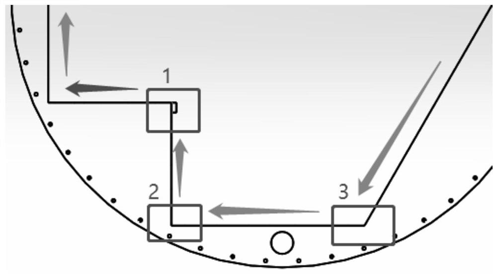
[0054] The aerial work robot is based on a lightweight design, so sector magnets are used. The company's existing magnetic adsorption robot magnets are fixed at the bottom of the robot, and can only move together with the robot, and cannot swing autonomously, so they cannot climb over figure 1 In 1, 2, 3 and similar positions, in order to solve these problems...


PUM


Abstract

The invention provides a design method of a magnet swinging device. According to the magnet swinging device designed by the method, on the basis of an existing driving wheel set of the robot, under the condition that no motor is added, a wheel set driving motor is used as power to achieve swinging of a magnet, an electromagnetic clutch is added between the magnet and the driving motor to control transmission of the power, and therefore the swinging angle of the magnet is controlled; when the magnet swings from one face to the other face, face turning of the robot can be achieved, and the magnet can be freely switched between free swing and active swing according to needs so that the robot can adapt to the requirement changes of different curvatures.

Description

technical field [0001] The present application relates to the technical field of aerial work robots, in particular to a design method of a magnet swinging device. Background technique [0002] Aerial working robots are based on lightweight designs, usually using sector magnets. The magnets installed on the existing magnetic adsorption robot are all fixed on the bottom of the robot, and can only move together with the robot, and cannot swing autonomously. Moreover, the existing robot chassis can move on large planes and surfaces with relatively small curvature, but cannot climb over adjacent surfaces whose angles are less than a certain value, such as figure 1 1, 2, 3 and similar positions shown in , that is, walking can only be realized between planes or surfaces with small angles, and walking between surfaces with large angles is basically impossible. In order to enable the robot to move on a surface with a relatively large curvature and smoothly climb over an adjacent su...

Claims


Application Information

Patent Timeline
IPC IPC(8): B62D57/024B25J11/00
CPCB62D57/024B25J11/00
Inventor 许华旸何承通宋章军卞丙祥吴迪刘彦雨郭超琼
Owner BEIJING SHIHE TECH CO LTD
Why Eureka
Try Eureka