Fastener testing device
A testing device and fastener technology, applied in the field of fastener testing devices, can solve the problems of no testing device and the inability to effectively evaluate the anti-loosening reliability of the fastening structure, and achieve the effect of improving the detection accuracy
- Summary
- Abstract
- Description
- Claims
- Application Information
AI Technical Summary
Problems solved by technology
Method used
Image

Examples
Embodiment 1
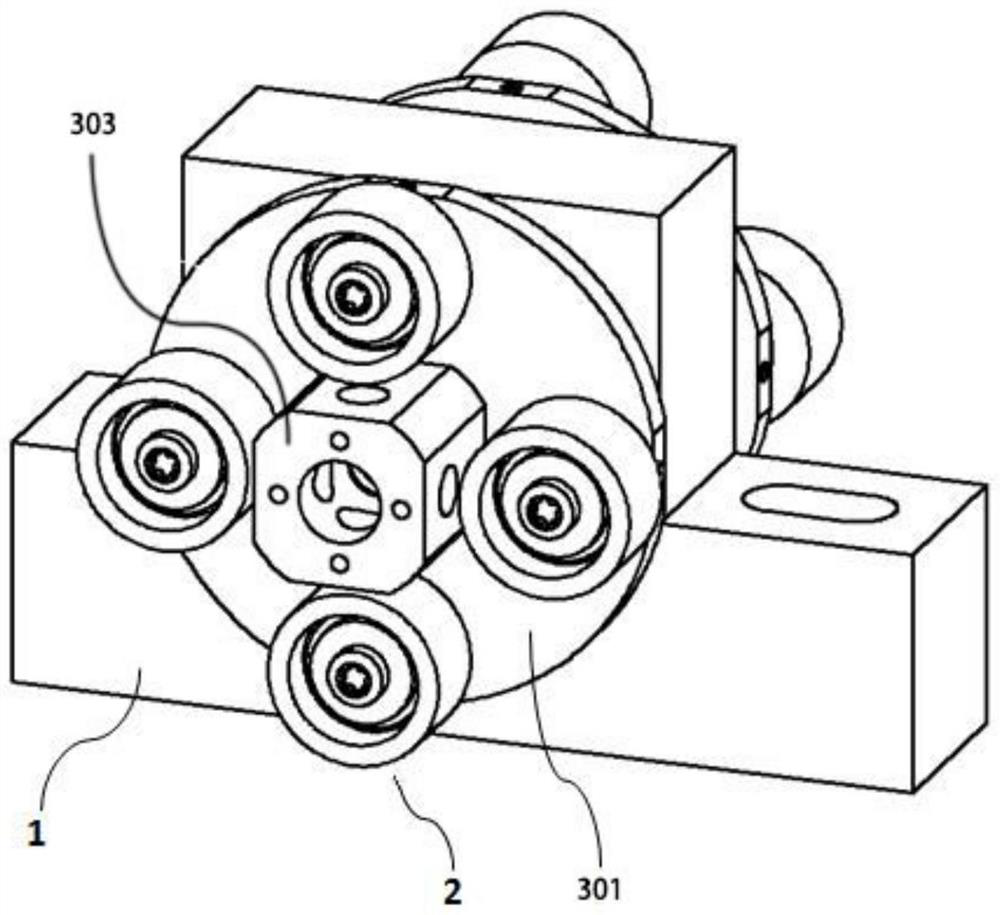
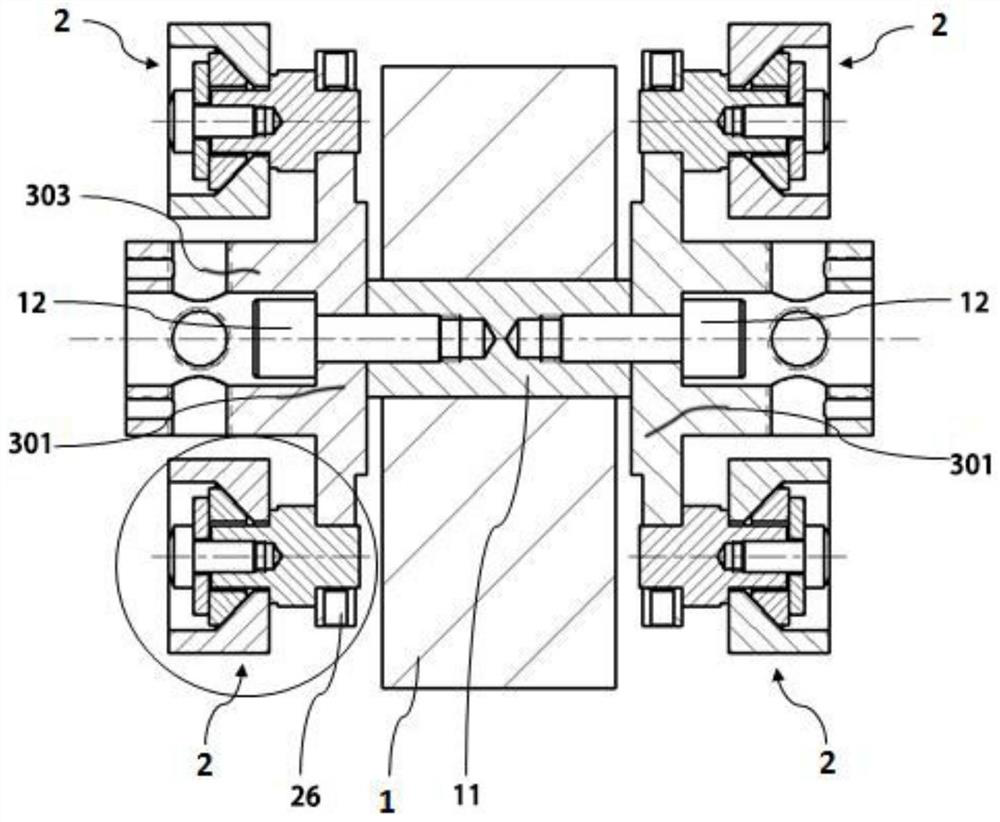
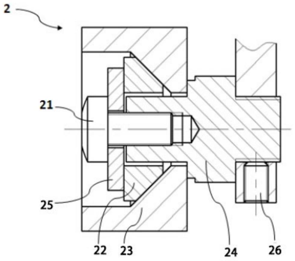
[0043] The present embodiment provides a fastener testing device, comprising a vibrating base 1 and a testing assembly 2; the vibrating base 1 is driven to reciprocate vibrating motion, and has a vibration direction; the testing assembly 2 is provided with a mounting position 21; the mounting position 21 is used for Install the fastener to be tested, have an axis, and be coaxial with the fastener to be tested; also include movable parts, in order to distinguish the movable parts of the following embodiment 2, the movable parts of this embodiment are named as the first movable parts; the described The first movable part is installed on the vibration base 1, and the vibration base 1 drives the first movable part to perform reciprocating impact movement along the vibration direction; the test assembly 2 is fixedly installed on the first movable part, and the axis is parallel to the vibration direction or forms an acute angle with the vibration direction.
[0044] The axis in this ...
Embodiment 2
[0055] This embodiment provides a fastener testing device. The difference from Embodiment 1 is that this embodiment is used for oblique testing. An acute angle with a fixed angle, the difference in the specific structure lies in the movable part, and the movable part in this embodiment is named as the second movable part.
[0056] like Figure 7 As shown, the second movable part includes a mounting base plate 301 and four wedge blocks 302 . The four wedges 302 protrude from the outer surface of the mounting base 301 and are evenly distributed around the central axis of the mounting base 301 in a cross shape. The outer surface of the installation base plate 301 is a vertical surface, and the outer surface of each wedge block 302 is an inclined plane. slope.
[0057] The test assembly 2 is arranged on the slope of the wedge-shaped block 302, the bottom of the counterweight 23 is closely attached to the slope, and the axis of the mounting position 21 in the opening cavity of t...
Embodiment 3
[0059] The evaluation indexes of conventional sleeve impact test for fasteners are loosening angle and loosening time. However, under certain conditions (such as the fastening process of yield point method), it is difficult for the fastener to be tested to loosen within the standard test time. The performance of the fastener cannot be evaluated at this time.
[0060] In order to overcome the shortcomings of the conventional sleeve impact test, and to take into account the influence of temperature on the performance of the fastener, this embodiment provides a test method for the fastener testing device of Embodiment 1 and 2. The specific steps are as follows:
[0061] 1) Select the material and surface of the counterweight to make the test components fit the assembly process and practical application; the test components will not be installed on the installation base for the time being;
[0062] 2) To test the static inspection torque T1, use a dial or digital display torque wr...
PUM
 Abstract
Description
Claims
Application Information
 - R&D
- Intellectual Property
- Life Sciences
- Materials
- Tech Scout
- Unparalleled Data Quality
- Higher Quality Content
- 60% Fewer Hallucinations
Browse by: Latest US Patents, China's latest patents, Technical Efficacy Thesaurus, Application Domain, Technology Topic, Popular Technical Reports.
© 2025 PatSnap. All rights reserved.Legal|Privacy policy|Modern Slavery Act Transparency Statement|Sitemap|About US| Contact US: help@patsnap.com