Binocular visual image stereo matching method

A binocular vision and stereo matching technology, applied in image enhancement, image analysis, image data processing, etc., can solve the problems of insufficient real-time performance and low precision

Inactive Publication Date: 2016-04-27
HEBEI UNIV OF TECH
View PDF4 Cites 29 Cited by
  • Summary
  • Abstract
  • Description
  • Claims
  • Application Information

AI Technical Summary

Problems solved by technology

The invention overcomes the defects of low matching accuracy and insuffic...

Method used


Image

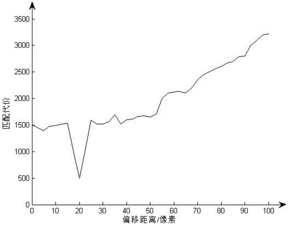
  • Binocular visual image stereo matching method
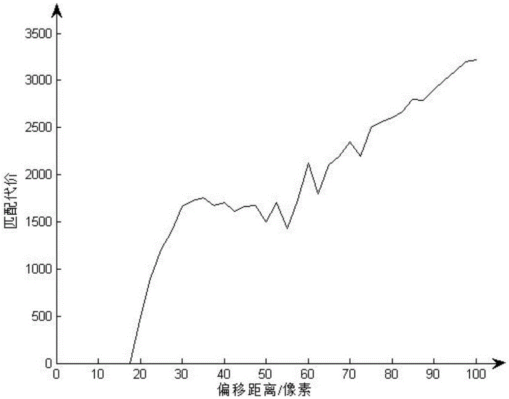
  • Binocular visual image stereo matching method
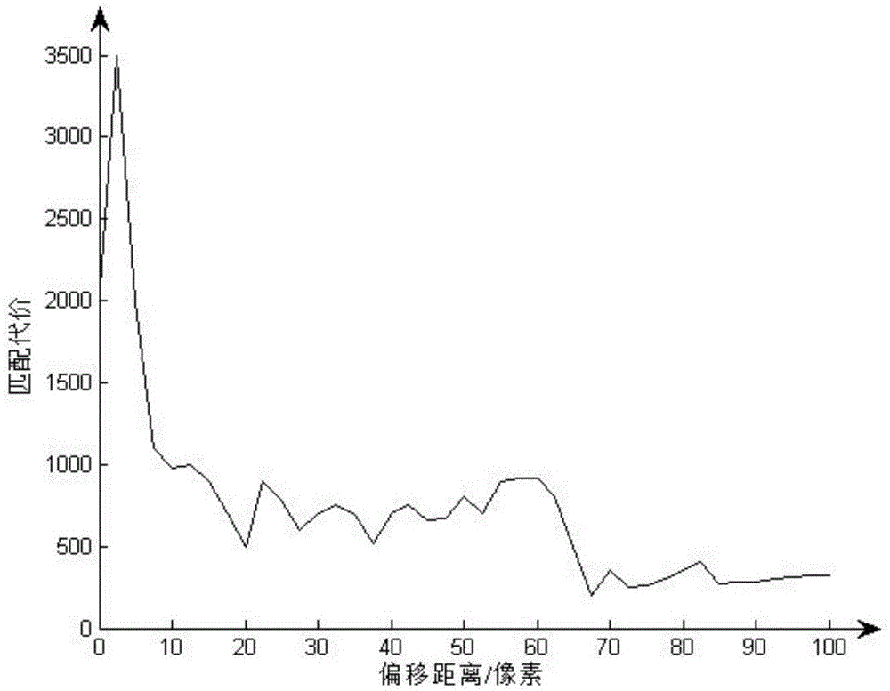
  • Binocular visual image stereo matching method

Examples


Embodiment 1

[0079] A kind of binocular vision image stereo matching method of the present embodiment, the steps are as follows:

[0080] The first step is the acquisition and preprocessing of binocular images:

[0081] The binocular image acquisition method is to extract the left and right views through two cameras that are relatively parallel in physical position; the preprocessing method is to normalize the extracted binocular image to 384×288 pixels, and then according to the calibration of the camera The parameters are used to correct the left and right views, using the Bouguet epipolar correction method to eliminate distortion and line alignment, so that the imaging origin coordinates of the left and right views are consistent, and the initial parameters are set for the corrected left and right images, and the left and right images are respectively Set as the matching image L and the image to be matched R, and set the maximum disparity value d max , the specific method is:

[0082]...


PUM


Abstract

The present invention discloses a binocular visual image stereo matching method, relating to image data processing. The method comprises the steps of the acquisition and pre-processing of a binocular image, the image gradient matrix solution of the binocular image, the obtainment of an initial disparity map, and the obtainment and output of a final disparity map and the completion of the binocular visual image stereo matching. According to the method, the defect of low matching precision and insufficient real-time performance of the existing binocular stereo matching technology is overcome.

Description

technical field [0001] The technical solution of the present invention relates to image data processing, in particular to a binocular vision image stereo matching method. Background technique [0002] Stereo vision technology is one of the key technologies in the field of mobile robot visual navigation. To navigate in an unknown environment, quickly and accurately identify obstacle information and plan a feasible path, the stereo matching algorithm of the stereo vision navigation system should have high accuracy. and real-time. In the past few decades, experts in the field of computer vision have conducted extensive and in-depth research on the problem of using stereo images to extract three-dimensional information of scenes, especially in the field of robot intelligence that has attracted widespread attention in recent years. It provides important decision-making information for the robot. [0003] Stereo matching algorithms can be divided into local stereo matching algor...

Claims


Application Information

Patent Timeline
IPC IPC(8): G06T7/00
CPCG06T2207/10012G06T2207/20021G06T2207/20228
Inventor 于明师硕于洋郭迎春刘依阎刚王佳希
Owner HEBEI UNIV OF TECH
Why Eureka
Try Eureka