
Smart city road auxiliary parking system

An auxiliary parking and urban technology, applied in the directions of indicating the various open spaces of the parking lot, instruments, ticketing equipment, etc., can solve the problems of scratch damage, the inability to quickly and timely find the location of the car, the lack of separation and positioning, etc., to increase the firmness. Effect

Inactive Publication Date: 2022-04-12
黄湘珍
View PDF0 Cites 0 Cited by
  • Summary
  • Abstract
  • Description
  • Claims
  • Application Information

AI Technical Summary

Problems solved by technology

[0002] At present, parking spaces are very important traffic measures in the city, and when the existing parking spaces are parked, the surroundings are directly exposed to the outside and lack the function of separation and positioning, especially for some drivers who are not very familiar with driving experience. Personnel, the sense of direction is not very good when parking, and they are not sure about the position and direction of movement when parking. It is easy to scratch the outside of the vehicle parked on both sides of the empty parking space during the parking process, and when parking Afterwards, one side of the car body is exposed to the side of the road. If the vehicle is not paying attention, it is easy to scratch the outside of the vehicle parked in the parking space and cause scratch damage. After parking, there are many parking spaces on the roadside. Moreover, the markings of the parking spaces are all written on the road. When picking up the car at night, it is impossible to quickly and timely find the location of the car. It is easy to cause excessive parking time and overcharging.

Method used


Image

  • Smart city road auxiliary parking system
  • Smart city road auxiliary parking system
  • Smart city road auxiliary parking system

Examples


Embodiment Construction

[0026] The following will clearly and completely describe the technical solutions in the embodiments of the present invention with reference to the accompanying drawings in the embodiments of the present invention. Obviously, the described embodiments are only some, not all, embodiments of the present invention. Based on the embodiments of the present invention, all other embodiments obtained by persons of ordinary skill in the art without making creative efforts belong to the protection scope of the present invention.

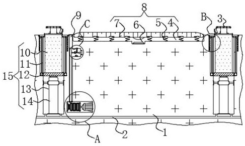
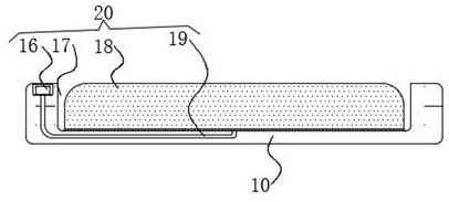
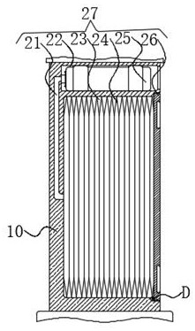
[0027] see Figure 1-8 , the present invention provides a technical solution: a smart city road auxiliary parking system, comprising a parking space surface 1, a trigger mechanism 8 is provided in the middle of the upper end of the parking space surface 1, and both sides of the upper end of the parking space surface 1 are provided with Vehicle distance positioning and separating mechanism 15, the upper ends of both sides of the vehicle distance positioning and...


PUM


Abstract

The invention discloses a smart city road auxiliary parking system which comprises a parking space surface, a triggering mechanism is arranged in the middle of the upper end of the parking space surface, vehicle distance positioning and separating mechanisms are arranged on the two sides of the upper end of the parking space surface, and supporting mechanisms are arranged at the upper ends of the two sides of each vehicle distance positioning and separating mechanism. When a positioning plate moves upwards, stable sliding blocks on the two sides are driven to move towards the upper ends of the interiors of stable sliding grooves, the stability of the positioning plate in the moving process is improved, and when the stable sliding blocks move upwards, a connecting rope is in a loose state, and a supporting block loses constraining force; the movable block, the movable supporting rod and the supporting block can be pushed to move upwards through the reset spring in an extruded state, the firmness of the positioning plate in the using process is improved through the movable supporting rod and the supporting block, and the situation that the positioning plate is toppled over and fractured due to impact in the using process is prevented.

Description

technical field [0001] The invention relates to the field of urban road traffic, in particular to a smart city road auxiliary parking system. Background technique [0002] At present, parking spaces are very important traffic measures in the city, and when the existing parking spaces are parked, the surroundings are directly exposed to the outside and lack the function of separation and positioning, especially for some drivers who are not very familiar with driving experience. Personnel, the sense of direction is not very good when parking, and they are not sure about the position and direction of movement when parking. It is easy to scratch the outside of the vehicle parked on both sides of the empty parking space during the parking process, and when parking Afterwards, one side of the car body is exposed to the side of the road. If the vehicle is not paying attention, it is easy to scratch the outside of the vehicle parked in the parking space and cause scratch damage. Aft...

Claims


Application Information

Patent Timeline
Patent Type & Authority Applications(China)
IPC IPC(8): G07B15/02G08G1/14
Inventor 黄湘珍
Owner 黄湘珍
Learn More