
Floating connector and manufacturing method thereof

A technology of floating connectors and floating blocks, which is applied in the direction of connection, parts of connection devices, fixed/insulated contact components, etc., which can solve the problems of large size and achieve the effect of increasing volume

Pending Publication Date: 2022-04-12
DACHANG ELECTRONICS TECH SUZHOU CO LTD
View PDF0 Cites 0 Cited by
  • Summary
  • Abstract
  • Description
  • Claims
  • Application Information

AI Technical Summary

Problems solved by technology

[0003] The traditional approach is that the connector is composed of multiple components, such as insertion guides, floating distances and floating retaining walls, etc., to achieve the purpose of floating by providing space between components; however, the traditional approach is , directly increase the space available for floating outside the structure of the original component, but the disadvantage is that the size of the original component becomes larger, resulting in extrusion to the setting of other components

Method used


Image

  • Floating connector and manufacturing method thereof
  • Floating connector and manufacturing method thereof
  • Floating connector and manufacturing method thereof

Examples


Embodiment Construction

[0047] In order to fully understand the purpose, features and effects of the present invention, the present invention will be described in detail by means of the following specific embodiments and accompanying drawings, as follows.

[0048] In the present invention, "a" or "an" is used to describe elements, elements and components described herein. This is done for convenience of description only and to provide a general sense of the scope of the invention. Therefore, unless it is obvious otherwise, such description should be read to include one, at least one, and the singular also includes a plurality.

[0049] In the present invention, the terms "comprises", "including", "has", "containing" or any other similar terms are intended to cover a non-exclusive inclusion. For example, an element, structure, article, or device that contains multiple elements is not limited to those elements listed herein, but may include elements that are not specifically listed but are generally i...


PUM


Abstract

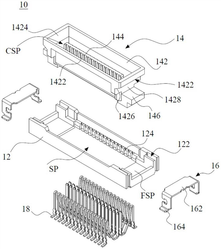
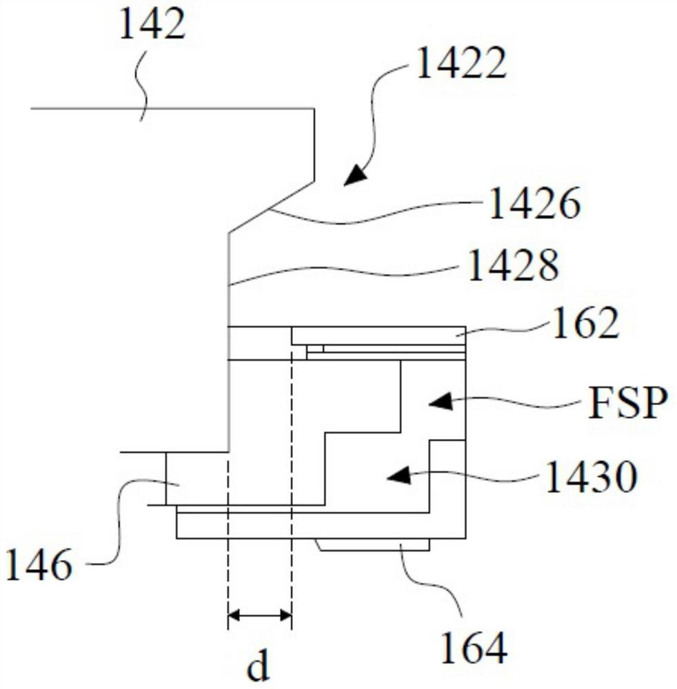
The invention relates to a floating connector. The floating connector comprises a first shell, a second shell, a limiting piece and a terminal, the first housing forms an accommodating space, a floating space and a slit. The second shell is provided with an insertion guide part, a tongue plate and a floating block; the second housing forms a connection space for arranging the tongue plate and exposing the tongue plate at the insertion guide part with the inner inclined surface. Concave parts with retaining walls are formed on the two side edges of the second shell respectively, and the floating blocks are formed on the two side edges of the second shell respectively and arranged in the floating space respectively. The limiting pieces are arranged in the slits respectively. The limiting piece and the retaining wall can determine the floating distance of the floating block in the floating space so as to limit the floating block to move in the floating space. The terminals are arranged in the accommodating space and the connecting space. The invention further provides a manufacturing method of the floating connector.

Description

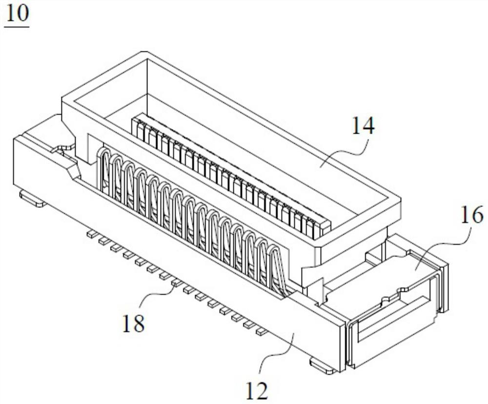
【Technical field】 [0001] The invention relates to the technical field of a floating connector, in particular to a small-sized floating connector and a manufacturing method thereof. 【Background technique】 [0002] For traditional connectors, in order to avoid damage to the connectors due to, for example, excessive application of external force during the assembly process by the user, a floating connector has been developed. [0003] The traditional approach is that the connector is composed of multiple components, such as insertion guides, floating distances and floating retaining walls, etc., to achieve the purpose of floating by providing space between components; however, the traditional approach is , directly increase the space available for floating outside the structure of the original component, but the disadvantage is that the size of the original component becomes larger, resulting in extrusion to the setting of other components. [0004] In view of this, the presen...

Claims


Application Information

Patent Timeline
Patent Type & Authority Applications(China)
IPC IPC(8): H01R13/631H01R13/502H01R13/40
Inventor 庄顺荣
Owner DACHANG ELECTRONICS TECH SUZHOU CO LTD
Learn More