Winding machine and winding method

A winding method and winding machine technology, applied in coil manufacturing, electrical components, inductance/transformer/magnet manufacturing, etc., can solve the problems of increasing the volume of transformers, increasing the thickness of coils, increasing the volume of electronic products, etc., to solve the problem of increasing volume , the effect of reducing thickness

Active Publication Date: 2017-02-01
BTCOIL ELECTRONICS (DONGGUAN) LIMITED
View PDF5 Cites 0 Cited by
  • Summary
  • Abstract
  • Description
  • Claims
  • Application Information

AI Technical Summary

Problems solved by technology

While the existing winding machine is winding, the wire is fed from one direction, and then the winding is completed by a single winding shaft. The terminals of the coil wound out in this way are located on the inner and outer surfaces of the coil. When using a coil, one of the terminals must cross the coil to get close to the other terminal, resulting in an increase in the thickness of the coil, thereby increasing the volume of the transformer, which in turn increases the volume of electronic products, which is not conducive to the development of electronic products in the direction of lightness and thinness.

Method used


Image

  • Winding machine and winding method
  • Winding machine and winding method
  • Winding machine and winding method

Examples


Embodiment Construction

[0044] The following will clearly and completely describe the technical solutions in the embodiments of the present invention with reference to the drawings in the embodiments of the present invention.

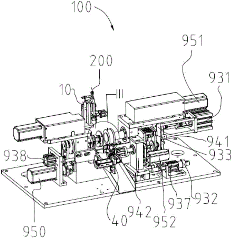
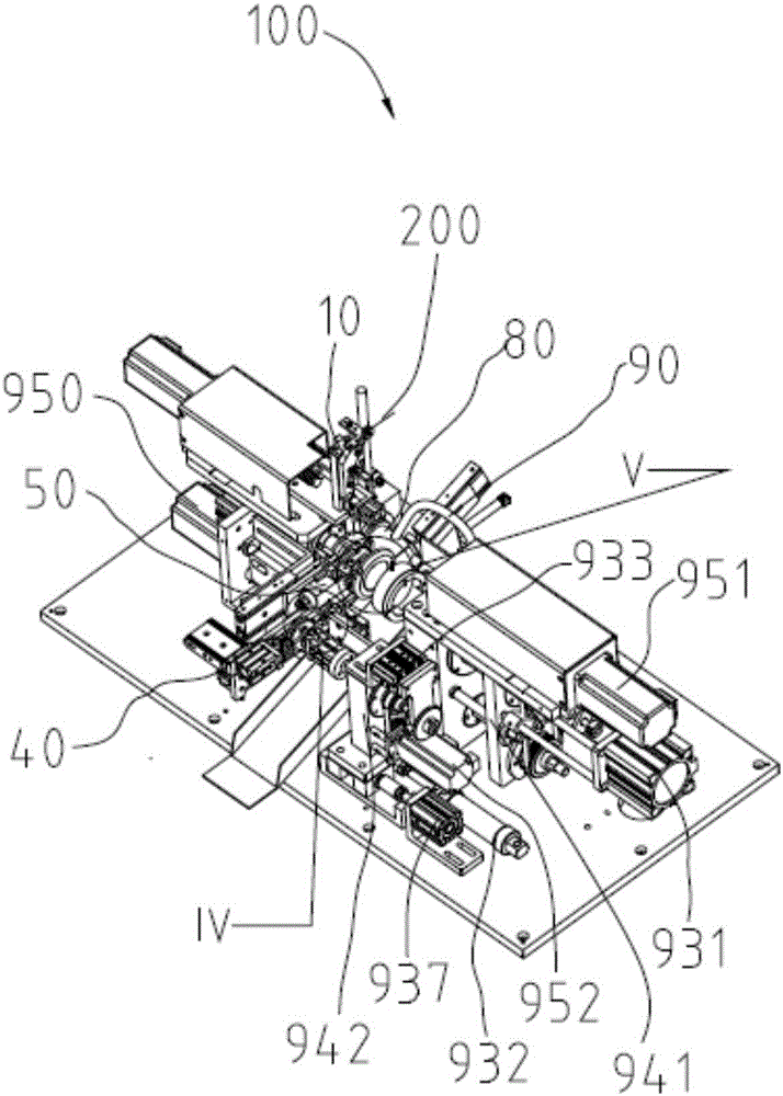
[0045] Please refer to figure 1 , the winding machine 100 provided by the present invention is used for winding N-layer coils, where N is an integer greater than or equal to 2.

[0046] In this embodiment, the N-layer coil is a 30-layer coil.

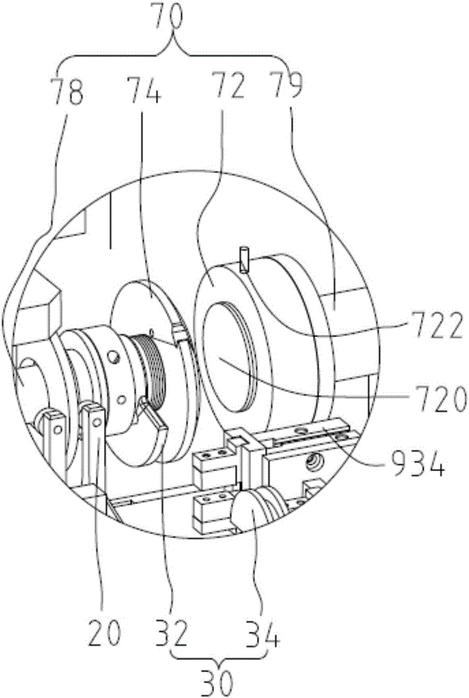
[0047] Please also refer to Figure 2 to Figure 4 , The winding machine 100 includes a wire arranging device 10 , a first wire pressing device 20 , a wire storage device 30 , a wire clamping device 40 , a wire cutting device 50 , a second wire pressing device 60 and a wire winding device 70 . The wire storage device 30 includes a first wire storage part 32 and a second wire storage part 34 , and the first wire pressing device 20 is installed on the first wire storage part 32 .

[0048] When winding, the wire arranging device 10 transpo...


PUM


Abstract

The invention discloses a wire winding machine, which comprises a wire displacement device, a first wire pressing device, a wire storage device, a wire clamping device, a wire cutting device, a second wire pressing device and a wire winding device, wherein the wire storage device comprises a first wire storage part and a second wire storage part, the wire displacement device conveys wire materials to the first wire pressing device for pressing wire ends, the wire displacement device conveys the wire materials to the first wire storage part for storing tail layer wire materials, the wire displacement device conveys the wire materials to the wire winding device, the wire winding device rotates to wind the wires, and in addition, the wire displacement device realizes the wire displacement, so that (N-1) layers are formed, the wire cutting device cuts the wire materials, the wire clamping device clamps the wire ends and conveys the wire ends to the second wire storage part, the second wire storage part presses the wire ends and stores tail layer wire materials, the second wire pressing device presses the wire materials between the wire winding device and the second wire storage part, and the wire winding device winds the wires for forming N layers of coils. The invention also provides a wire winding method. The wire winding machine and the wire winding method provided by the invention have the advantages that the N layers of coils are wound in two layers, so that the two wire joints are respectively positioned on the outer surfaces of the N layer of coils, and the wire connection is favorably realized.

Description

technical field [0001] The invention relates to a winding machine, in particular to a winding machine and a winding method for multilayer coils. Background technique [0002] In general electronic products, such as mobile phones, computers, etc., transformers are required, and coils are used in transformers. The volume of coils affects the volume of transformers, thereby affecting the volume of electronic products. While the existing winding machine is winding, the wire is fed from one direction, and then the winding is completed by a single winding shaft. The terminals of the coil wound out in this way are located on the inner and outer surfaces of the coil. When using a coil, one of the terminals must cross the coil to get close to the other terminal, resulting in an increase in the thickness of the coil, thereby increasing the volume of the transformer, which in turn increases the volume of electronic products, which is not conducive to the development of electronic produ...

Claims


Application Information

Patent Timeline
Patent Type & Authority Patents(China)
IPC IPC(8): H01F41/066H01F41/082H01F41/098H01F41/06
Inventor 朱承义
Owner BTCOIL ELECTRONICS (DONGGUAN) LIMITED
Why Eureka
Try Eureka