Cable bridge

A cable bridge and bridge technology, applied in the direction of electrical components, etc., can solve the problem that the cable bridge is difficult to practice and automatically lay cables, etc., and achieve the effects of reducing labor costs, good applicability, and improving efficiency

Pending Publication Date: 2022-04-12
宁波信杰电缆桥架有限公司
View PDF0 Cites 2 Cited by
  • Summary
  • Abstract
  • Description
  • Claims
  • Application Information

AI Technical Summary

Problems solved by technology

[0003] The purpose of the present invention is to provide a cable tray to solve the problem that the cable tray in the prior art is difficult to practice automatic laying of cables

Method used


Image

  • Cable bridge
  • Cable bridge
  • Cable bridge

Examples


Embodiment Construction

[0026] The present invention will be described in further detail below in conjunction with the accompanying drawings and specific embodiments.

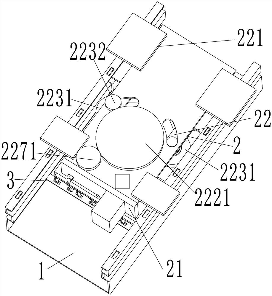
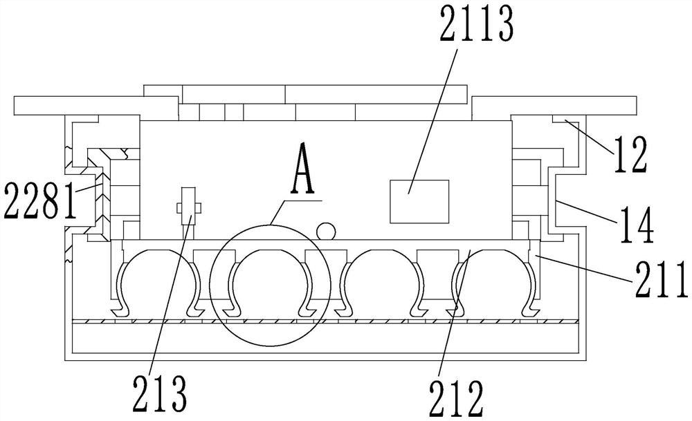
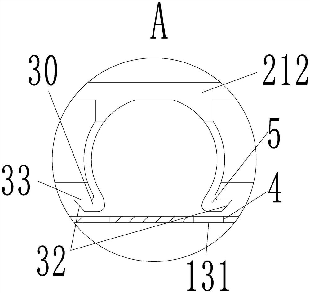
[0027] Depend on Figure 1 to Figure 9 As shown, the cable bridge of the present invention includes a bridge body 1, a wiring device 2 and a plurality of fixing rings 3; There are a plurality of reinforcing ribs 13 for fixing cables, the length direction of each reinforcing rib 13 is parallel to the width direction of the bottom plate 101, and each reinforcing rib 13 is arranged in groups of two along its length direction. A plurality of fixing grooves 131; each fixing ring 3 is provided with an opening, and both sides of the opening are provided with buckle parts 30;

[0028] The specific wiring process is as follows:

[0029] 1. Preparatory work: When laying cables, first manually pull out the starting ends of multiple cables from the pay-off device, and fix them on the front end of the bridge frame in advance, and then set the sa...


PUM


Abstract

The invention discloses a cable bridge which comprises a bridge body, a wiring device and a plurality of fixing rings. The bridge body comprises a bottom plate and two side plates perpendicular to the bottom plate, a plurality of reinforcing ribs used for fixing cables are sequentially arranged on the bottom plate in the length direction, the length direction of each reinforcing rib is parallel to the width direction of the bottom plate, and a plurality of fixing grooves are formed in each reinforcing rib in the length direction in a mode that every two reinforcing ribs form a group. Each fixing ring is provided with an opening, and buckling parts are arranged on the two sides of each opening; the fixing ring is automatically controlled through the wiring device to lock each section of cable on the corresponding reinforcing rib for wiring, manual wiring is replaced, the labor cost is reduced, and the efficiency is greatly improved; the multiple sliding grooves are formed in the wiring installation block, wiring work can be conducted on multiple cables at the same time, the structure is simplified, and efficiency is improved.

Description

technical field [0001] The invention relates to the field of electric power construction, in particular to a cable tray. Background technique [0002] With the rapid development of people's living standards, cable trays are used more and more in power construction; cable trays are composed of straight sections, bends, components, and brackets (arm brackets) and hangers of pallets or ladders. A rigid structural system with close-fitting support cables. At present, the laying of cables in cable trays is mainly done manually by climbing ladders. This method is not safe and has low efficiency; therefore, it is of great practical significance to design a cable tray with an automatic routing device. Contents of the invention [0003] The object of the present invention is to provide a cable tray to solve the problem that the cable tray in the prior art is difficult to practice automatic laying of cables. [0004] In order to solve the above technical problems, the cable bridge...

Claims


Application Information

Patent Timeline
IPC IPC(8): H02G3/04
Inventor 陈杰伟彭庞伟单冰冰
Owner 宁波信杰电缆桥架有限公司
Why Eureka
Try Eureka