Progressive centrifugal machine blade machining auxiliary equipment

A technology of auxiliary equipment and centrifuges, which is applied in the field of centrifuges, can solve the problems of affecting product quality, difficulty in adjusting the angle of centrifuge blades, and different degrees of bending, so as to achieve the effect of saving manpower

Inactive Publication Date: 2022-04-15
聂新柳
View PDF0 Cites 0 Cited by
  • Summary
  • Abstract
  • Description
  • Claims
  • Application Information

AI Technical Summary

Problems solved by technology

[0004] In order to overcome the sore hands of the workers after long-term operation, the workers do not bend the centrifuge blades enough during subsequent operations, which will cause the bending degree of each blade to be different, which will affect the quality of subsequent products. It is also difficult to achieve consistent adjustment of centrifuge blade angle. The invention provides a progressive centrifuge blade processing auxiliary equipment

Method used


Image

  • Progressive centrifugal machine blade machining auxiliary equipment
  • Progressive centrifugal machine blade machining auxiliary equipment
  • Progressive centrifugal machine blade machining auxiliary equipment

Examples


Embodiment 1

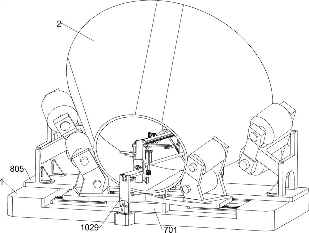
[0033] A progressive centrifuge blade processing auxiliary equipment such as Figure 1-3 As shown, it includes a U-shaped base 1, a limit cover 2, a bending mechanism, a transmission mechanism and an auxiliary mechanism; the upper part of the U-shaped base 1 is provided with a limit cover 2; the upper part of the U-shaped base 1 is equipped with a bending mechanism; the bending mechanism The right part is connected with a transmission mechanism; the lower side of the rear part of the bending mechanism is connected with an auxiliary mechanism; the transmission mechanism is connected with the auxiliary mechanism.

[0034] Working process: When working, place the U-shaped base 1 horizontally so that the high sides of the U-shaped base 1 are at the same level as the ground, then connect the external power supply, and the operator will transport the centrifuge blades into the bending mechanism and auxiliary mechanism, and pass the limit Cover 2, the bending mechanism and the auxili...

Embodiment 2

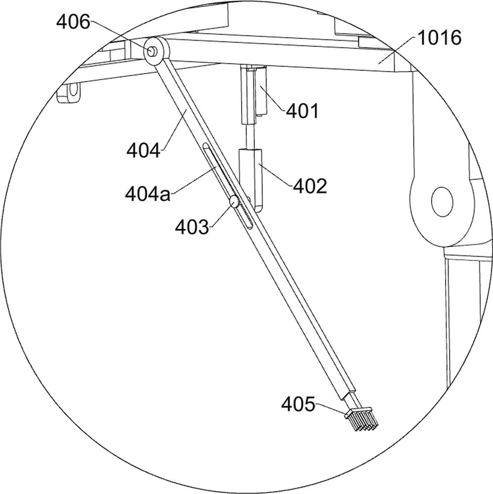
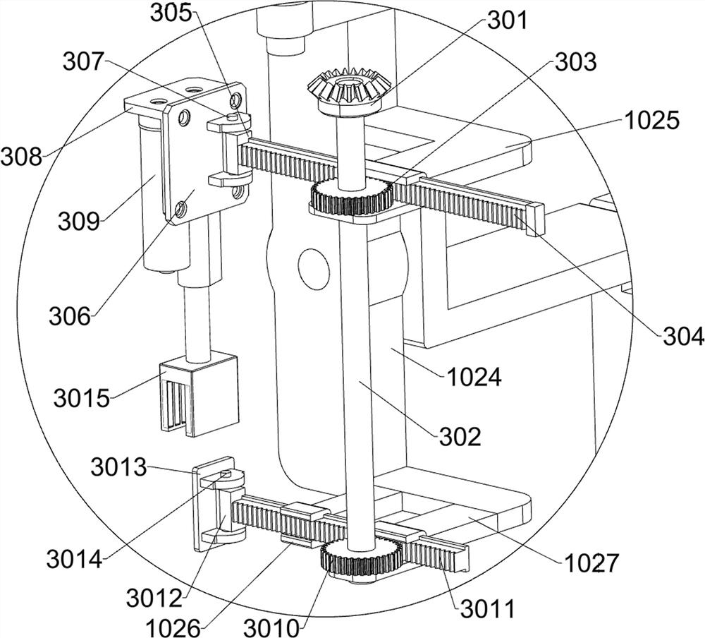
[0036] On the basis of Example 1, such as Figure 4-7 As shown, the bending mechanism includes a tripod wheel 101, a leg 102, a cross base 103, a handle 104, a driver 105, a first swing frame 106, a horizontal plate 107, a first bracket 108, a second bracket 109, a first electric slide Rail 1010, first electric slider 1011, first guide rail 1012, first moving block 1013, second guide rail 1014, second moving block 1015, first moving plate 1016, first electric push rod 1017, first U-shaped block 1018, the third guide rail 1019, the first mounting plate 10191, the second mounting plate 10192, the third mounting plate 10193, the first bidirectional rack 1020, the second bidirectional rack 1021, the third bidirectional rack 1022, the rotating rod 1023, The second swing frame 1024, the first bracket 1025, the second bracket 1026, the third bracket 1027, the rotating plate 1028, the riser 1029, the third support 1030, the fourth support 1031 and the third moving block 1032; U-shaped...

Embodiment 3

[0043] On the basis of Example 2, such as figure 1 and Figure 8-12 As shown, it also includes a lifting mechanism, the upper side of the U-shaped base 1 is connected with a lifting mechanism, and the lifting mechanism includes a fixed plate 701, a first elastic member 702, a first support plate 703, a first supporting plate 704, The second support plate 705, the second elastic member 706, the third elastic member 707, the third support plate 708, the second support plate 709, the fourth support plate 7010 and the fourth elastic member 7011; the upper middle part of the U-shaped base 1 The fixed plate 701 is welded; the upper side of the fixed plate 701 is connected with four first elastic members 702 distributed in a rectangular shape; each of the upper ends of the four first elastic members 702 is connected with a first support plate 703; A first supporting plate 704 is welded between the plates 703 and between the two first supporting plates 703 on the right; the two first...


PUM


Abstract

The invention relates to the field of centrifugal machines, in particular to progressive centrifugal machine blade machining auxiliary equipment. The technical problems that hands of workers are prone to ache after long-time operation, the bending strength of the workers on blades of the centrifugal machine is insufficient during follow-up operation, the bending degrees of all the blades are different, the quality of follow-up products is affected, and meanwhile the angles of the blades of the centrifugal machine are difficult to be adjusted to be consistent manually during bending are solved. According to the technical scheme, the blade production device for the centrifugal machine comprises a U-shaped base, a limiting cover and the like; and a limiting cover is arranged above the U-shaped base. According to the centrifugal machine blade bending device, bending machining of centrifugal machine blades is achieved, the radian of the centrifugal machine blades at different positions can be automatically adjusted during bending, the centrifugal machine blades are bent and formed at a time, meanwhile, manpower can be saved, and bending of the centrifugal machine blades can be achieved without cooperation of multiple persons.

Description

technical field [0001] The invention relates to the field of centrifuges, in particular to a progressive centrifuge blade processing auxiliary equipment. Background technique [0002] At present, in the processing of centrifuge blades, the centrifuge blades are first bent and then welded. Due to the high quality of the blades, it takes many people to hold the blades for a long time to cooperate with each other when the blades are bent. The part is sore, and the long-term operation will cause the workers to bend the centrifuge blades insufficiently, which will cause the bending degree of each blade to be different, which will affect the quality of subsequent products. The adjustment of the angle is also difficult to achieve consistency, which has a great impact on the safety and quality of the finished product, and also greatly wastes manpower; [0003] To sum up, there is an urgent need for a progressive centrifuge blade processing auxiliary equipment to solve the above pro...

Claims


Application Information

Patent Timeline
Patent Type & Authority Applications(China)
IPC IPC(8): B21D11/10B21D53/78
CPCB21D11/10B21D53/78
Inventor 聂新柳
Owner 聂新柳
Why Eureka
Try Eureka