
Rotary machine head type wire bending equipment

A technology of rotary joints and machine heads, applied in metal processing equipment, feeding devices, positioning devices, etc., can solve the problems of inability to achieve continuous processing and poor flexibility, and achieve continuous processing and improve equipment flexibility.

Inactive Publication Date: 2012-04-25
XI'AN UNIVERSITY OF ARCHITECTURE AND TECHNOLOGY
View PDF0 Cites 0 Cited by
  • Summary
  • Abstract
  • Description
  • Claims
  • Application Information

AI Technical Summary

Problems solved by technology

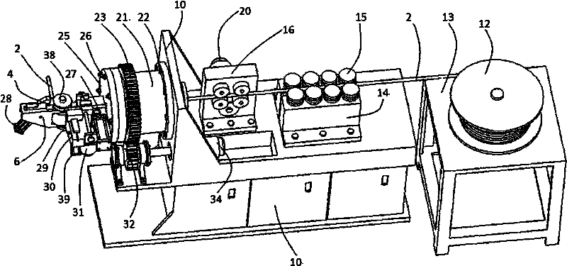
[0005] In order to overcome the shortcomings of poor flexibility of existing wire bending machine equipment and the inability to realize continuous processing, the present invention provides an improved structure of wire bending equipment. On the premise of not increasing the number of equipment, the wire bending equipment not only realizes continuous processing, Moreover, the bending length of the wire (pipe) is not limited by the structure of the equipment, and it can bend workpieces of any length.

Method used


Image

  • Rotary machine head type wire bending equipment
  • Rotary machine head type wire bending equipment
  • Rotary machine head type wire bending equipment

Examples


Embodiment Construction

[0024] The present invention will be described in further detail below in conjunction with the accompanying drawings.

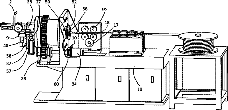
[0025] Such as figure 2 As shown, the rotary head type wire bending equipment of the present invention includes a frame 10 and a feeding mechanism 7, a fixed mold base 30 and a crank mechanism 6 installed on the frame 10 for bending the wire 2, wherein: as As an improvement to the existing structure, a straightening device and a feeding device are provided on the frame 10, and the feeding end of the feeding device is connected to a rotating device, and the driven gear 23 arranged on the rotating device is connected to the frame. The active pinion 32 on the 10 is meshed, and the 32 axles of the active pinion are connected with the motor 34 output shafts fixed on the frame 10 to realize power transmission; Hand mechanism 6, shears 27, support die 35, curved hand mechanism 6 and shears 27 cooperate support die 35 to realize the bending and cutting of wire rod ...


PUM


Abstract

The invention discloses rotary machine head type wire bending equipment, which comprises a machine frame, a material feeding mechanism, a fixed mold seat and a bending hand mechanism, wherein the material feeding mechanism, and the fixed mold seat and the bending hand mechanism are arranged on the machine frame and are used for wire bending on wire materials. The invention is characterized in that a straightening device and a feeding device are arranged on the machine frame, the conveying end of the feeding device is connected with a rotating device, a driven gearwheel arranged on the rotating device is engaged with a driving pinion connected on the machine frame, a wheel shaft of the driving pinion is connected with a motor output shaft fixed on the machine frame for realizing motive power transmission, in addition, the end surface of the rotating device is connected with a machine head frame, the bending hand mechanism, a shearing device and a support mold are arranged on the machine head frame, the bending hand mechanism and the shearing device are matched with the support mold for realizing the bending and the shearing on the wire materials, the wire bending equipment uses a motor to output the motive power, the driving pinion drives the driven gearwheel, a rotary joint and the machine head frame to rotate, the rotation movement of the machine head frame correspondingly tothe wire materials is realized, the rotary machine head type wire bending equipment is matched with the feeding mechanism to realize the continuous processing, and the equipment flexibility is improved.

Description

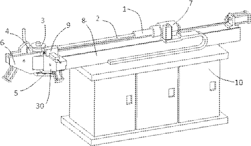
technical field [0001] The invention relates to a modification of a wire bending machine, in particular to a rotating head type wire bending device capable of bending wire rods in three-dimensional space. Background technique [0002] Commonly used wire bending machines that can bend and process wires (tubes) in three-dimensional space, such as figure 1 As shown, when performing the bending process of the wire (pipe) material in the three-dimensional space, one end of the wire (pipe) material 2 is first clamped by the chuck 1, and the other end passes through the fixed mold 9 on the fixed mold base 30, Placed on the main wheel mold 3, clamped by the fixed mold 9, the bending mold 4 is close to the wire (pipe) material 2, the transmission element 5 drives the crank mechanism 6 to rotate at a certain angle to realize bending processing, and at the same time, the feeding mechanism 7 Move along the guide rail 8 to drive the wire (pipe) material 2 to feed an appropriate distance...

Claims


Application Information

Patent Timeline
Patent Type & Authority Patents(China)
IPC IPC(8): B21F1/00B21F23/00B21D7/08B21D43/08
Inventor 吴晓君韩刚郑丹凤张晋文郑超
Owner XI'AN UNIVERSITY OF ARCHITECTURE AND TECHNOLOGY
Learn More