
A kind of steel mesh bending equipment

A steel mesh bending technology, applied in the field of steel mesh bending equipment, can solve the problems that the minimum bending side length is difficult to meet the standard design requirements, cannot cooperate with the steel mesh, and has a low degree of automation, etc., to achieve flexible bending angles Adjustable, wide range of bending angles, and the effect of reducing labor costs

Active Publication Date: 2021-03-05
BEIJING INST OF CONSTR MECHANIZATION +1
View PDF10 Cites 0 Cited by
  • Summary
  • Abstract
  • Description
  • Claims
  • Application Information

AI Technical Summary

Problems solved by technology

[0003] Compared with the traditional processing method, the existing bending machine has improved the production efficiency to a certain extent, but there are still the following problems: it can only realize the single-side bending processing of the steel mesh; the degree of automation is low, and the bending angle needs to be realized through manual control ; The minimum side length of the bending is difficult to meet the standard design requirements; it cannot cooperate with other equipment to realize the automatic insertion of the steel mesh; when bending the skeleton with overlapping parts, it is necessary to manually add lateral force to prevent the steel bar from interfering

Method used


Image

  • A kind of steel mesh bending equipment
  • A kind of steel mesh bending equipment
  • A kind of steel mesh bending equipment

Examples


Embodiment Construction

[0033] The following will clearly and completely describe the technical solutions in the embodiments of the present invention in conjunction with the accompanying drawings. Obviously, the described embodiments are only some of the embodiments of the present invention, not all of them. Based on the embodiments of the present invention, all other embodiments obtained by persons of ordinary skill in the art without making creative efforts belong to the protection scope of the present invention.

[0034] In the description of this patent, it is to be understood that the terms "center", "upper", "lower", "front", "rear", "left", "right", "vertical", "horizontal", The orientation or positional relationship indicated by "top", "bottom", "inner", "outer", etc. is based on the orientation or positional relationship shown in the drawings, and is only for the convenience of describing this patent and simplifying the description, rather than indicating or implying References to devices or...


PUM


Abstract

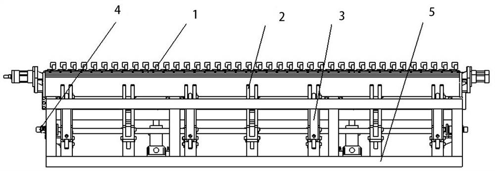
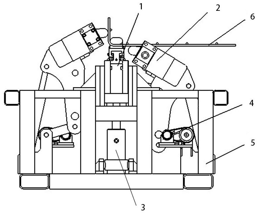
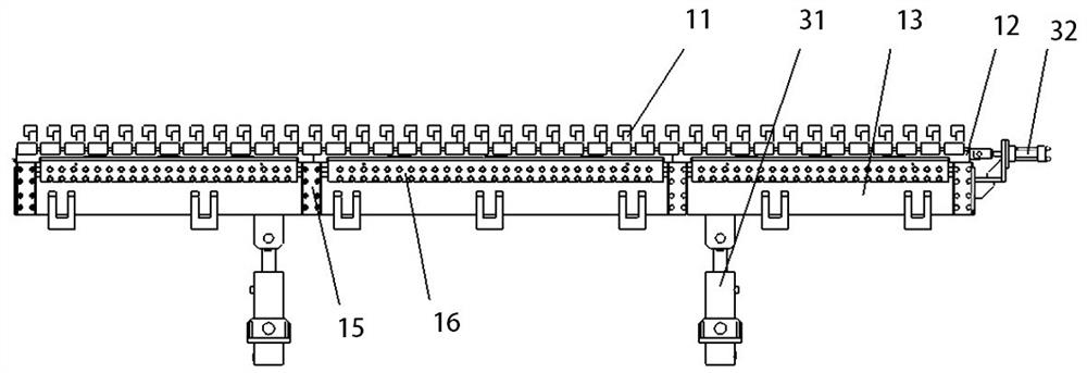
The invention discloses a steel mesh bending equipment, which comprises a mandrel mechanism, a bending arm mechanism, a driving mechanism, a counting mechanism and a frame; side, the bending arm mechanism and the mandrel mechanism are arranged parallel to each other; the driving mechanism includes a longitudinal driving mechanism, a transverse driving mechanism and a bending driving mechanism, the longitudinal driving mechanism drives the mandrel mechanism to move up and down, and the bending driving mechanism drives the connecting rod of the bending arm mechanism seat movement, the transverse drive mechanism drives the mandrel mechanism and the bending arm mechanism to move left and right; the counting mechanism is arranged on the bending arm mechanism. The invention sets two bending arm mechanisms to realize double-sided continuous and automatic bending of steel mesh sheets of different specifications, which is suitable for bending steel mesh of different specifications; through the cooperation of the driving mechanism and the counting mechanism, the continuous controllability of the bending process is realized. It has the advantages of flexible and adjustable bending angle and a wide range of bending angles, and can realize ultra-short side length bending.

Description

technical field [0001] The invention relates to the technical field of steel bar processing, in particular to a steel bar mesh bending equipment. Background technique [0002] Steel mesh with folded edges and rectangular steel cage are widely used in construction projects, and their production quality and production efficiency will directly affect the quality of the project and the length of the construction period. The traditional processing method of hemmed steel mesh and rectangular steel cage is mainly to use a single steel bar to bend and process into a hemmed steel bar or stirrup, and then bind and fix it with the main reinforcement in the arranged position. With the emergence of the bending machine, the processing method of bending the prefabricated steel mesh to form the steel mesh with folded edges and the rectangular steel cage has been widely used. [0003] Compared with the traditional processing method, the existing bending machine has improved the production e...

Claims


Application Information

Patent Timeline
Patent Type & Authority Patents(China)
IPC IPC(8): B21D11/12B21D11/22B21C51/00
CPCB21C51/00B21D11/125B21D11/22
Inventor 汶浩刘子金侯爱山王振丰赵红学肖飞王辉纪恩龙贾晨光苑柳依张东斌翟晓东钟文海岳巍巍
Owner BEIJING INST OF CONSTR MECHANIZATION
Learn More