
Intelligent electromagnetic welding machine monitoring device

A technology of monitoring device and welding machine, which is applied in the direction of cooling/ventilation/heating transformation, etc. It can solve the problems of fixed mode use, equipment damage, and the failure of automatic reporting of location information by welding machines, so as to achieve the effect of increasing heat dissipation efficiency

Active Publication Date: 2022-04-15
WUHAN NEWFIBER OPTOELECTRONICS TECH
View PDF5 Cites 0 Cited by
  • Summary
  • Abstract
  • Description
  • Claims
  • Application Information

AI Technical Summary

Problems solved by technology

[0002]Electromagnetic welding equipment uses hot-melt connection to connect parts that need to be fixed. The existing welding machine number, equipment operating process parameters and equipment operating voltage , unable to achieve automatic display and alarm functions, and personnel cannot monitor the data of the equipment itself during use, which may easily cause damage to the equipment. In addition, the existing fusion splicers cannot automatically report location information, which is inconvenient for personnel to conduct inspections when they are on business trips. And when in use, it is impossible to remotely lock and unlock the equipment in the charged state, remotely modify the process parameters of the fusion splicer, and need to review and confirm when modifying, which is inconvenient to use. A large amount of heat is generated, and the existing monitoring equipment is installed inside the fusion splicer, which cannot dissipate heat quickly, thus easily causing damage to the monitoring device, and it is not possible to use different adjustment and fixing methods for the fixed space while dissipating heat, which is inconvenient to use

Method used


Image

  • Intelligent electromagnetic welding machine monitoring device
  • Intelligent electromagnetic welding machine monitoring device
  • Intelligent electromagnetic welding machine monitoring device

Examples


Embodiment approach

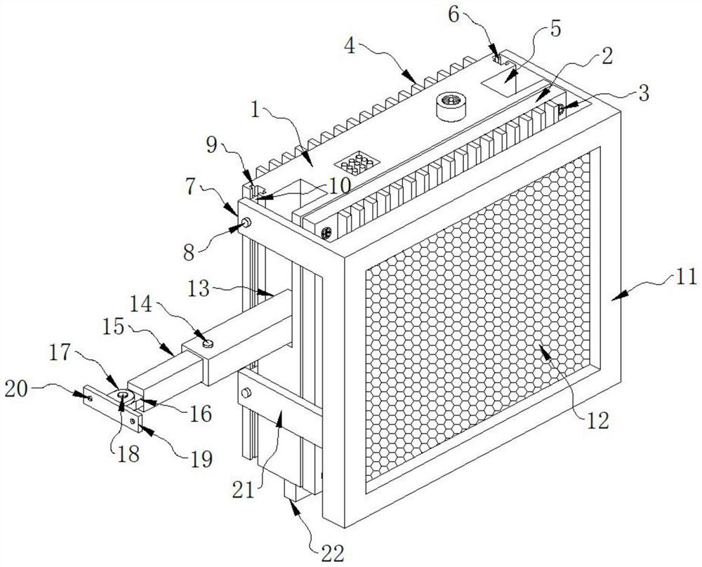
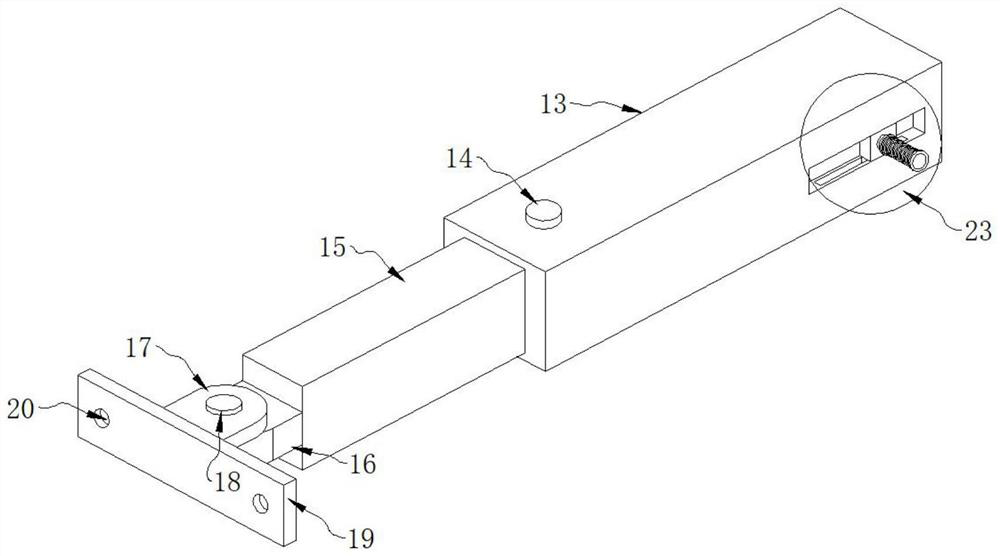
[0029] As a preferred embodiment of the present invention, a cooling plate 22 is installed on the bottom of the fixed box 1, and an oblique hole 37 is opened on the cooling plate 22, and connecting devices 23 are installed on both sides of the fixing rod 13, so that The fixing rod 13 is installed inside the opening 5 through the connecting device 23 .

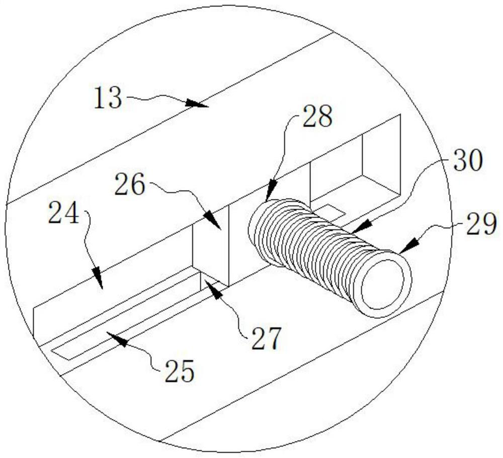
[0030] As a preferred embodiment of the present invention, the connection device 23 includes a chute 24, a slider 26 is installed inside the chute 24, and a block 27 is installed on the slider 26, so A groove 25 is formed on the inner wall of the first chute 24, and the clamping block 27 is installed in the groove 25.

[0031] As a preferred embodiment of the present invention, an inner rod 28 is fixed on the slider one 26, an outer rod 29 is fixed on the inner rod 28, and a torsion spring is installed between the outer rod 29 and the inner rod 28. 30, the two ends of the torsion spring 30 are respectively fixed on the inner r...


PUM


Abstract

The invention provides an intelligent electromagnetic welding machine monitoring device which comprises a monitoring device body, the monitoring device body comprises a fixing box, a cover plate is installed on one side of the fixing box, the cover plate is installed on the fixing box through bolts, fin plates are fixed to one side of the fixing box and one side of the cover plate, openings are formed in the two sides of the fixing box, and the fin plates are fixed to the fixing box through bolts. An open groove is formed in one side of the opening, a protruding block is installed in the open groove, and a limiting block is welded to the protruding block. When the intelligent electromagnetic welding machine monitoring device is used, the supporting plate drives the fixing plate to move downwards, after the fixing plate moves downwards, the bottom of the heat dissipation fan is exposed, the heat dissipation fan is matched with an inclined hole in the heat dissipation plate, rapid heat dissipation of two fin plates is achieved, and the heat dissipation efficiency is improved; the positions of the fixed plate and the movable plate can be adjusted through the fastening bolts, when the fixed plate and the movable plate are adjusted, the inclination angle of the fixed rod can be limited for use, and supporting and fixing in different spaces are met.

Description

technical field [0001] The invention relates to the field of monitoring equipment, in particular to a monitoring device for an intelligent electromagnetic welding machine. Background technique [0002] Electromagnetic welding equipment uses hot-melt connection to connect parts that need to be fixed. The existing welding machine number, equipment operating process parameters and equipment operating voltage cannot achieve automatic display and alarm functions. The data monitoring of the equipment itself can easily cause damage to the equipment. In addition, the existing fusion splicer cannot automatically report the positioning information, which is inconvenient for personnel to conduct inspections when they are on business trips, and when in use, it is impossible to remotely lock and unlock the equipment in the charged state. Operation and remote modification of the process parameters of the fusion splicer require review and confirmation during modification, which is inconven...

Claims


Application Information

Patent Timeline
Patent Type & Authority Applications(China)
IPC IPC(8): B29C37/00H05K7/20
Inventor 沈欢武治国潘凌平张伟徐锦锋张春萍徐凯张振扬
Owner WUHAN NEWFIBER OPTOELECTRONICS TECH
Learn More