
Improved new energy charging pile device

A new energy and charging pile technology, applied in charging stations, electric vehicle charging technology, electric vehicles, etc., can solve the problems of reducing the service life of equipment, exposure to the outside, and reducing safety performance, so as to improve service life, improve practicability, The effect of improving safety

Inactive Publication Date: 2022-04-15
徐州丰和新能源科技有限公司
View PDF0 Cites 0 Cited by
  • Summary
  • Abstract
  • Description
  • Claims
  • Application Information

AI Technical Summary

Problems solved by technology

[0003] Nowadays, the charging guns matched with electric vehicles are correspondingly developing rapidly. Electric vehicles are charged through the charging cable cable when charging. The core of the charging gun is the charging gun head connected to the car, and people use the charging gun head to After the car is fully charged, it is often easy to forget to put the charging head in place due to negligence, exposing it to the outside, thereby reducing the service life of the device and reducing its safety performance, and the charging head on the traditional charging pile cannot It automatically returns to the original position, so there are certain potential safety hazards, and it cannot meet the needs of users. Therefore, it is necessary to further improve

Method used


Image

  • Improved new energy charging pile device
  • Improved new energy charging pile device
  • Improved new energy charging pile device

Examples


Embodiment 1

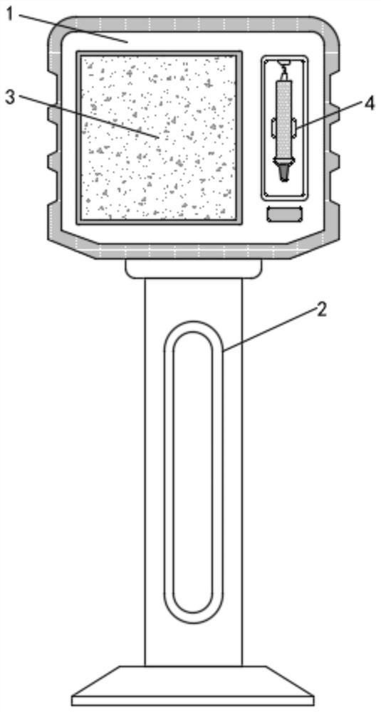
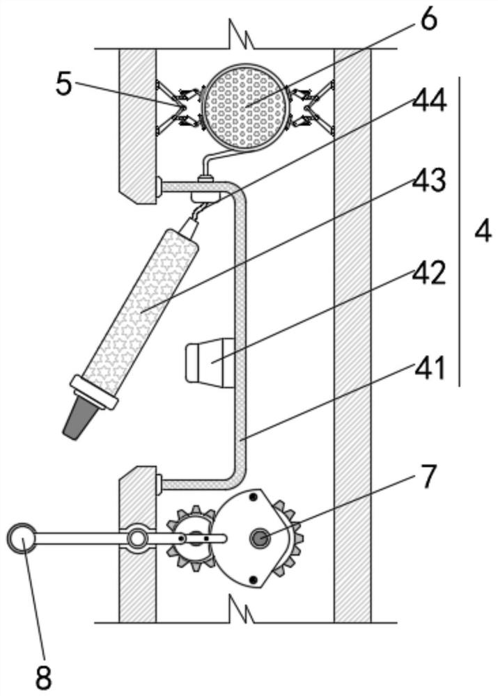
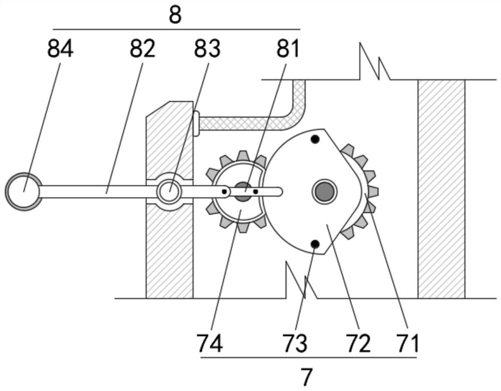
[0028] see figure 1 and Figure 4 and Figure 5 , an improved new energy charging pile device, including a control box 1, the interior of the control box 1 is equipped with a gear linkage assembly 7 and a pressing auxiliary assembly 8, and the gear linkage assembly 7 includes a first gear 71 and a second gear 74 , and a fixed plate 72 is installed on the first gear 71, and a fixed piece 73 is fixedly installed on the fixed plate 72. The pressing auxiliary assembly 8 includes a movable connecting rod 81, and the movable connecting rod 81 is used in conjunction with the fixed piece 73. The left end of the connecting rod 81 is movably connected with a movable rod 82 , the movable rod 82 is installed in cooperation with the control box 1 through the movable shaft 83 , and the left end of the movable rod 82 is fixedly equipped with a pressing positioning mechanism 84 .

[0029] Further, the inside of the control box 1 is equipped with an induction mechanism 5, and a wire take-up ...

Embodiment 2

[0036] see Figure 1 to Figure 5 , an improved new energy charging pile device, including a control box 1, the interior of the control box 1 is equipped with a gear linkage assembly 7 and a pressing auxiliary assembly 8, and the gear linkage assembly 7 includes a first gear 71 and a second gear 74 , and a fixed plate 72 is installed on the first gear 71, and a fixed piece 73 is fixedly installed on the fixed plate 72. The pressing auxiliary assembly 8 includes a movable connecting rod 81, and the movable connecting rod 81 is used in conjunction with the fixed piece 73. The left end of the connecting rod 81 is movably connected with a movable rod 82 , the movable rod 82 is installed in cooperation with the control box 1 through the movable shaft 83 , and the left end of the movable rod 82 is fixedly equipped with a pressing positioning mechanism 84 .

[0037] Further, a fixed support frame 2 is fixedly installed on the bottom of the control box 1 , a control panel 3 is installe...


PUM


Abstract

The invention provides an improved new energy charging pile device which comprises a control box body, a gear linkage assembly and a pressing auxiliary assembly are installed in the control box body, the gear linkage assembly comprises a first gear and a second gear, a fixing plate is movably installed on the first gear, a fixing piece is fixedly installed on the fixing plate, and the pressing auxiliary assembly is fixedly installed on the fixing piece. The pressing auxiliary assembly comprises a movable connecting rod, and the movable connecting rod is used in cooperation with the fixing piece. According to the improved new energy charging pile device, when a rotating shaft stalls, based on the centrifugal force effect, a centrifugal assembly on the outer side of a first mounting part moves outwards, the outer end of a centrifugal part makes contact with a buffering part, meanwhile, a buffering connecting rod is used for driving a speed reduction part to move relatively, and the speed reduction part makes contact with the centrifugal part; therefore, the rotating shaft is subjected to speed reduction treatment, the situation that the rotating shaft stalls, and consequently a take-up component is damaged in the cable recycling process is avoided, and the safety of equipment is improved.

Description

technical field [0001] The invention belongs to the technical field of new energy vehicle charging piles, and in particular relates to an improved new energy charging pile device. Background technique [0002] With the improvement of people's living standards, and the current trend of environmental protection, energy saving, and green ecological earth, electric vehicles are developing more and more powerfully with the strong support of the country, and their applications are becoming more and more extensive. The new energy vehicle industry is a major force in my country. It is a new type of industry developed, which has attracted people's attention for its many advantages such as energy saving and low exhaust emissions. [0003] Nowadays, the charging guns matched with electric vehicles are correspondingly developing rapidly. Electric vehicles are charged through the charging cable cable when charging. The core of the charging gun is the charging gun head connected to the car...

Claims


Application Information

Patent Timeline
Patent Type & Authority Applications(China)
IPC IPC(8): B65H75/44B60L53/31B60L53/18
CPCY02T10/70Y02T10/7072Y02T90/12Y02T90/14
Inventor 王怀亮
Owner 徐州丰和新能源科技有限公司
Learn More