
Inertia friction welding device capable of freely adjusting inertia of flywheel

A friction welding and flywheel technology, applied in welding equipment, non-electric welding equipment, metal processing equipment, etc., can solve the problems of unable to adjust the flywheel speed, slow downtime, frequent replacement of flywheels, etc., to save labor and time for replacing flywheel discs , increase the welding speed, reduce the use and maintenance costs

Active Publication Date: 2022-03-08
NO 59 RES INST OF CHINA ORDNANCE IND
View PDF6 Cites 0 Cited by
  • Summary
  • Abstract
  • Description
  • Claims
  • Application Information

AI Technical Summary

Problems solved by technology

[0004] In view of the above existing problems in the prior art, the object of the present invention is to provide an inertial friction welding device that can freely adjust the inertia of the flywheel, so as to solve the problem that the existing inertial friction welding equipment in the above-mentioned background technology needs to frequently replace the flywheel and cannot weld The speed adjustment of the flywheel during the process and the problem of slow stop speed in specific or unexpected situations

Method used


Image

  • Inertia friction welding device capable of freely adjusting inertia of flywheel
  • Inertia friction welding device capable of freely adjusting inertia of flywheel
  • Inertia friction welding device capable of freely adjusting inertia of flywheel

Examples


Embodiment

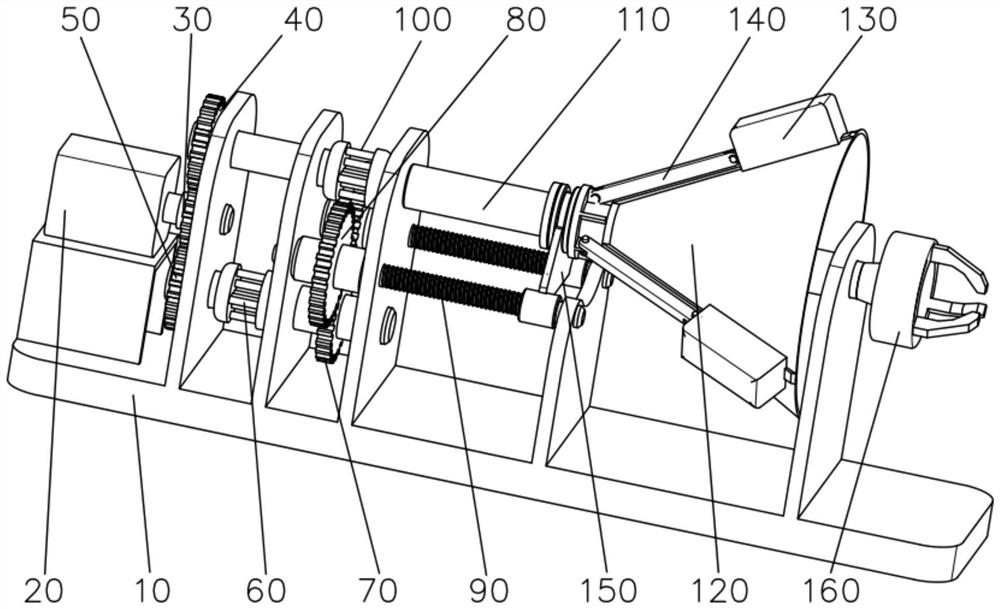
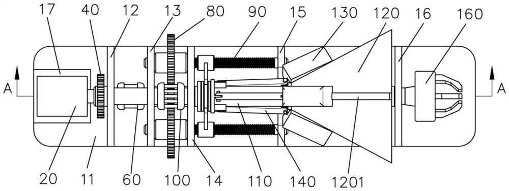
[0032] Such as Figure 1-8 As shown, an inertial friction welding device for freely adjusting flywheel inertia is characterized in that it includes a main body bracket 10, a motor 20, a driving gear 30, a first driven gear 40, a second driven gear 50, a lead screw clutch 60, The third driven gear 70, the fourth driven gear 80, the ball screw 90, the main shaft clutch 100, the main shaft 110, the conical flywheel disc 120, the mass slider 130, the connecting rod 140 and the driving assembly 150;

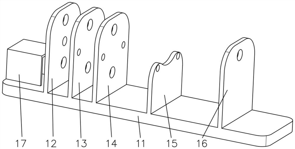
[0033] The main body bracket 10 includes a base 11, a gear bracket 12, a clutch bracket 13, a rotating shaft bracket 14, a screw bracket 15 and a main shaft bracket 16; the upper end surface of the base 11 is from left to right (such as figure 1 , figure 2 As shown), the gear bracket 12, the clutch bracket 13, the rotating shaft bracket 14, the lead screw bracket 15 and the main shaft bracket 16 are fixedly arranged in sequence;

[0034] The end of the output end of the motor 20 is...


PUM


Abstract

The invention provides an inertia friction welding device capable of freely adjusting the inertia of a flywheel. The inertia friction welding device comprises a main body support (10), a motor (20), a driving gear (30), a first driven gear (40), a second driven gear (50), a lead screw clutch (60), a third driven gear (70), a fourth driven gear (80), a ball screw (90), a main shaft clutch (100), a main shaft (110), a conical flywheel disc (120), a mass sliding block (130), a connecting rod (140) and a driving assembly (150). The main body support (10) comprises a base (11), a gear support (12), a clutch support (13), a rotating shaft support (14), a lead screw support (15) and a main shaft support (16). The device effectively solves the problems that in existing inertia friction welding equipment, flywheels need to be replaced frequently, the speed of the flywheels cannot be adjusted in the welding process, and the shutdown speed is low under specific or emergency situations.

Description

technical field [0001] The invention relates to the technical field of friction welding devices, in particular to an inertia friction welding device that can freely adjust the inertia of a flywheel. Background technique [0002] Friction welding refers to the use of the friction heat generated by the friction between thermoplastic materials (that is, the two workpieces to be welded will rotate and rub against each other under a certain friction force to generate heat), so that the friction surface is heated and melted, and then pressurized and welded. After cooling, a welded joint is formed, which can connect two workpieces to be welded together to achieve fusion welding; in the friction welding process, the required frictional heat is related to frictional pressure, rotational speed, time and frictional surface. Inertial friction welding is to clamp the moving workpiece on the flywheel, use the motor to apply power to the flywheel to reach a certain speed, then the motor is...

Claims


Application Information

Patent Timeline
Patent Type & Authority Applications(China)
IPC IPC(8): B23K20/12
CPCB23K20/1245B23K20/125Y02E60/16
Inventor 李忠盛吴护林陈大军黄安畏丛大龙刘正涛彭菲菲李辉吴厦江波
Owner NO 59 RES INST OF CHINA ORDNANCE IND
Learn More