Phototube test automation device and method

A test device and photoelectric tube technology, which is applied in the direction of single semiconductor device testing, etc., can solve the problems of rod-shaped photoelectric tube breakdown, photoelectric tube bursting and hurting people, etc., and achieve the effect of avoiding tube bursting accidents and reliable test environment

Pending Publication Date: 2022-04-15
淮安昕锐至新光电科技合伙企业(有限合伙)
View PDF0 Cites 1 Cited by
  • Summary
  • Abstract
  • Description
  • Claims
  • Application Information

AI Technical Summary

Problems solved by technology

[0005] Aiming at the deficiencies of the prior art, the present invention provides an automatic device and method for photoelectric tube testing, which solves the problem that the rod-shaped photoelectric tube is broken down when the rod-shaped photoelectric tube is energized, and the photoelectric tube may burst and hurt people.

Method used


Image

  • Phototube test automation device and method
  • Phototube test automation device and method
  • Phototube test automation device and method

Examples


Embodiment Construction

[0033] The present invention will be further described in detail below in conjunction with the accompanying drawings and specific embodiments. The embodiments of the present invention have been presented for purposes of illustration and description, but are not intended to be exhaustive or to limit the invention to the form disclosed. Many modifications and changes will be apparent to those of ordinary skill in the art. The embodiment was chosen and described in order to better explain the principles of the invention and the practical application, and to enable others of ordinary skill in the art to understand the invention and design various embodiments with various modifications as are suited to the particular use.

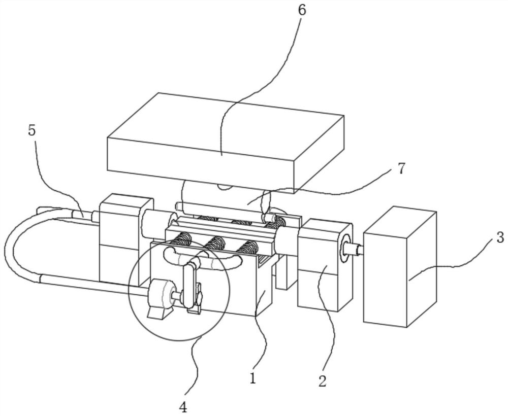
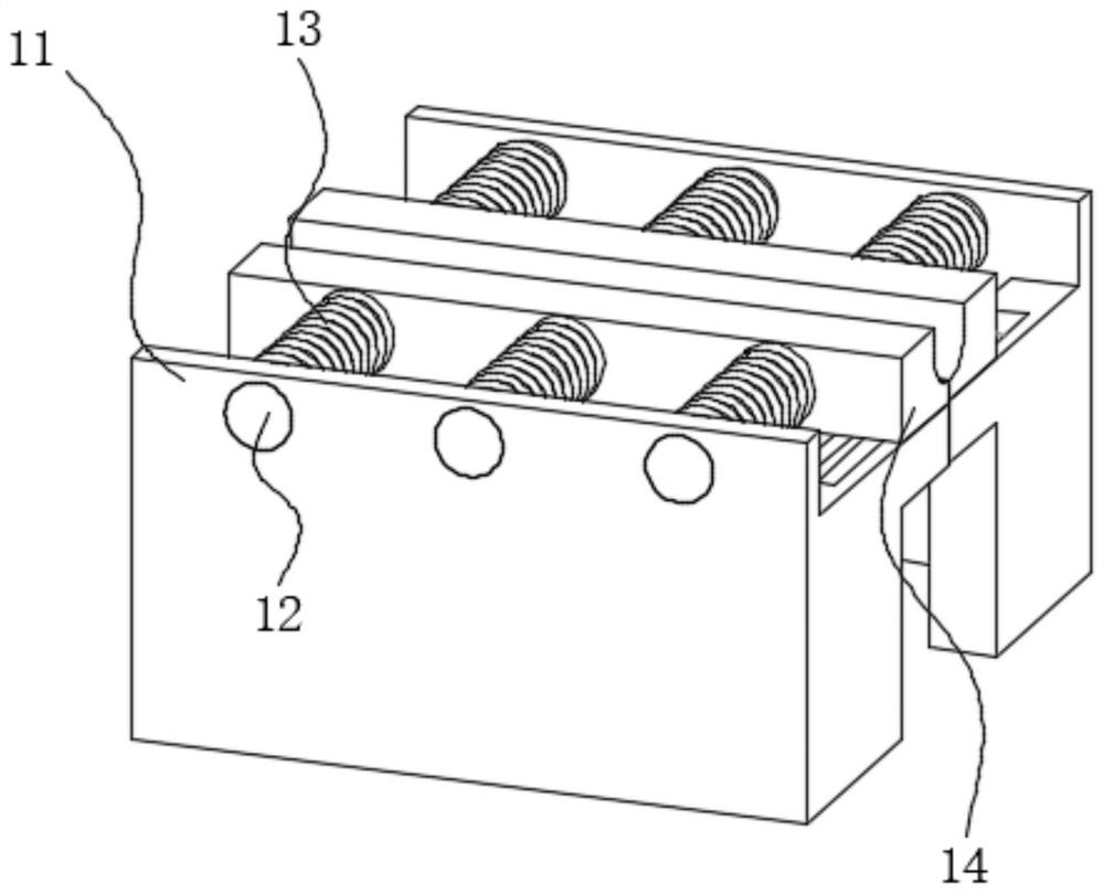
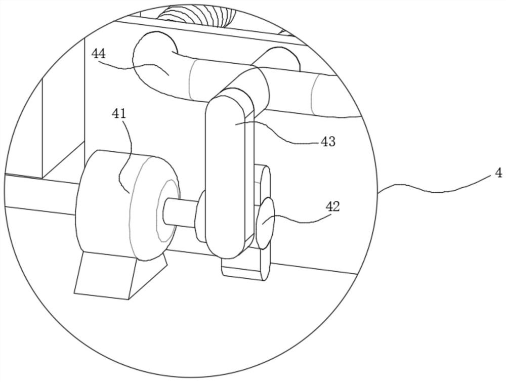
[0034] use Figure 1-Figure 7 A photoelectric cell test automation device and method according to an embodiment of the present invention will be described as follows.

[0035] Such as Figure 1-Figure 7 As shown, a photoelectric cell testing device according ...


PUM


Abstract

The invention belongs to the field of detection devices, and particularly relates to a photoelectric tube test automation device and method.The photoelectric tube test automation device comprises a combination table, power devices are symmetrically arranged on the front side and the rear side of the outer surface of the combination table, conductors are fixedly connected to the left sides of the outer surfaces of the power devices, and a supporting frame is fixedly connected to the right side of the outer surface of the combination table; the right side of the supporting frame is fixedly connected with a control power source through a connecting wire. The device can detect each processed to-be-detected pipe body in a flow mode, compared with manual detection, the possibility that an operator gets an electric shock when the to-be-detected pipe body is broken down due to unqualified quality is effectively reduced, the device can be remotely operated by the operator in the process of detecting the to-be-detected pipe body in a power-on mode, the detection conditions of all the to-be-detected pipe bodies are the same, and the detection efficiency is improved. Namely, the electrified parts and the placement positions are the same, and the temperature control conditions are the same, so that the test environment is more reliable, and the problem of test result deviation caused by unfixed electrified positions during manual detection is avoided.

Description

technical field [0001] The invention belongs to the field of detection devices, in particular to a photoelectric cell test automation device and method. Background technique [0002] Photoelectric tubes are basic photoelectric conversion devices based on the external photoelectric effect. Photoelectric tubes can convert light signals into electrical signals. Photoelectric tubes are divided into vacuum photoelectric tubes and gas-filled photoelectric tubes. The typical structure of photoelectric tubes is a spherical glass shell that is evacuated into a vacuum , a layer of photoelectric material is coated on the inner hemisphere as the cathode, and a small spherical or small ring metal is placed in the center of the sphere as the anode. [0003] The existing rod-shaped photoelectric tube needs to be energized and tested after production to ensure the quality of the phototube, but this operation requires manual installation and placement, and after the inspection is completed, ...

Claims


Application Information

Patent Timeline
Patent Type & Authority Applications(China)
IPC IPC(8): G01R31/26
Inventor 傅威靳贺迎胡克文何正洲
Owner 淮安昕锐至新光电科技合伙企业(有限合伙)
Why Eureka
Try Eureka