Quick-assembly welding-free LED lamp strip connector
A technology for LED light strips and light strips, which is applied in the direction of connection, coupling device, and parts of the connection device, etc., can solve the problems of difficult operability, large operating space, and inconvenient operation.
- Summary
- Abstract
- Description
- Claims
- Application Information
AI Technical Summary
Problems solved by technology
Method used
Image
Examples
Embodiment 1
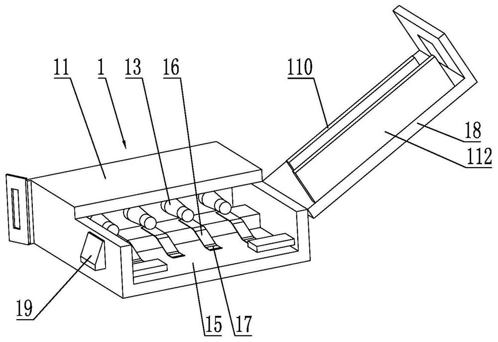
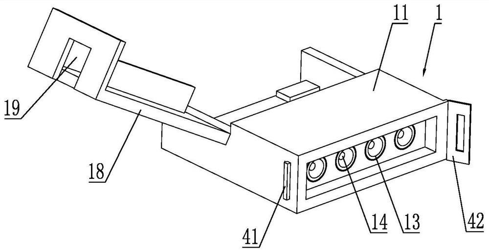
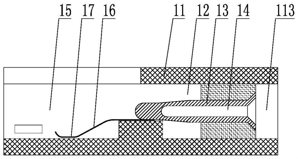
[0042] Such as figure 1 , figure 2 with image 3As shown, the fast-installation solderless LED light strip connector is installed at the end of the light strip 3 and correspondingly matched with the light strip wire end 31, including the connector body 11, and one side of the connector body 11 is provided with a socket for fixing Position 12, the socket fixing position 12 is fixed with conductive sockets corresponding to the number of lead wire ends 31 of the light strip, and the outer ends of the conductive sockets are respectively connected to the conductive pins of the PIN needle connector 2 21 plug fit; the conductive socket includes at least two conductive plug parts 13 arranged side by side, and each conductive plug part 13 is provided with a conductive plug hole corresponding to the end of the PIN needle connector 2 14. The conductive insertion hole 14 is set towards the direction of the PIN needle connector 2. In this embodiment, there are four conductive insertion...
Embodiment 2
[0061] The difference between the second embodiment and the first embodiment is only that: the number of the conductive plug-in parts 13 and the conductive plug-in holes 14 is different, and other structures are the same. see Figure 11 , in the second embodiment, the number of the conductive plug-in parts 13 and the conductive plug-in holes 14 is three, so the number of the elastic conductive strips 16 and the conductive pins 21 are three. Similarly, when the number of the conductive plug-in portion 13 and the conductive plug-in hole 14 is two, the number of the elastic conductive strip 16 and the conductive pin 21 are both two.
Embodiment 3
[0063] The difference between the third embodiment and the first embodiment is that: the end of the joint body 11 corresponding to the PIN connector 2 is provided with a connector receiving groove 113 for accommodating the PIN connector 2 . When the connector accommodating groove 113 is not provided, refer to the state after plugging Figure 9 , the connector base body 22 is exposed outside, rainwater is easy to enter into the mating surface between the conductive socket and the conductive pins 21, and the use safety is low.
[0064] In this embodiment, the structure of the connector receiving groove 113 corresponds to the connector base body 22. Since the connector base body 22 has a rectangular structure, the connector receiving groove 113 is correspondingly set as The rectangular structure that can accommodate the connector seat 22, the structure of the connector receiving groove 113 can be found in image 3 with Figure 5 , the connector accommodating groove 113 is arran...
PUM
| Property | Measurement | Unit |
|---|---|---|
| thickness | aaaaa | aaaaa |
Abstract
Description
Claims
Application Information
 - R&D
- Intellectual Property
- Life Sciences
- Materials
- Tech Scout
- Unparalleled Data Quality
- Higher Quality Content
- 60% Fewer Hallucinations
Browse by: Latest US Patents, China's latest patents, Technical Efficacy Thesaurus, Application Domain, Technology Topic, Popular Technical Reports.
© 2025 PatSnap. All rights reserved.Legal|Privacy policy|Modern Slavery Act Transparency Statement|Sitemap|About US| Contact US: help@patsnap.com


