Blood collection equipment for promoting blood circulation based on annular heating

A blood collection and annular technology, applied in tourniquets, medical devices, heating devices for treatment and other directions, can solve the problems of blood donor discomfort, long queues, single function, etc., to promote blood circulation and facilitate puncture. Enter, ensure the effect of relaxation

Pending Publication Date: 2022-04-19
JILIN UNIV FIRST HOSPITAL
View PDF0 Cites 0 Cited by
  • Summary
  • Abstract
  • Description
  • Claims
  • Application Information

AI Technical Summary

Problems solved by technology

[0002] With the increase of people's awareness of blood donation, mobile blood donation stations are set up in many places in the society. The general blood donation stations use needles and needle tubes to make blood flow into the blood bag. The blood flow rate in the hospital is slow, which will affect the speed of blood collection, especially in blood donation stations, if the blood collection is slow, there will be long queues, which will undoubtedly cause unnecessary trouble for blood donors
[0003] In the existing technology, a heating body, such as a heating wire, is usually installed in the wristband, and then the wristband is worn on the arm to promote blood flow through heating, but it does not take into account that the skin is relatively tight in a cold environment. This will cause discomfort to blood donors when the needle is inserted, and the functions brought by the bracelet are too single, for example:
[0004] It is impossible to use a heated environment to cooperate with alcohol wiping;
[0005] Unable to use the bracelet to complete hemostasis, etc.

Method used


Image

  • Blood collection equipment for promoting blood circulation based on annular heating
  • Blood collection equipment for promoting blood circulation based on annular heating
  • Blood collection equipment for promoting blood circulation based on annular heating

Examples


Embodiment 1

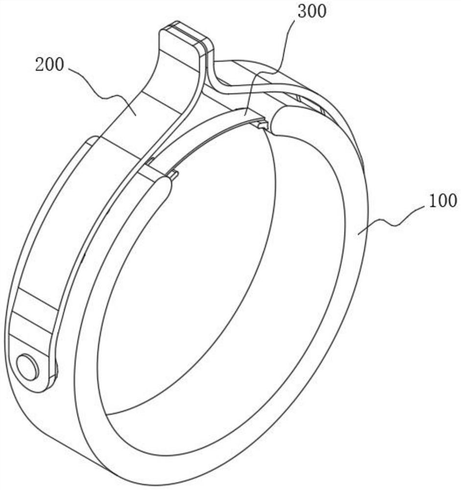
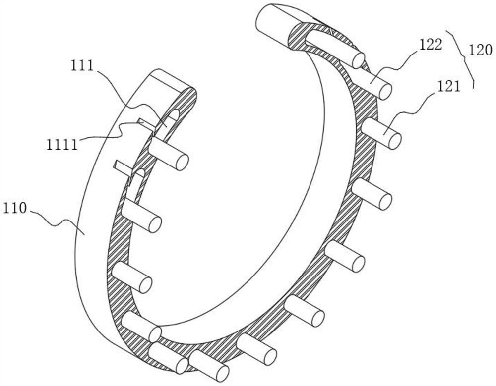
[0048] see figure 1 As shown, the purpose of this embodiment is to provide a blood collection device based on annular heating to promote blood circulation, which includes a warming mechanism 100, please refer to image 3 As shown, the heating mechanism 100 includes a heating ring 110 with an opening and a heating body group 120. The purpose of the opening is to facilitate the entry of the arm into the heating ring 110. The heating body group 120 is arranged along the path of the heating ring 110. Specifically of:

[0049] The heating body group 120 includes a fixed heating body 121 and a polycondensation heating body 122. The polycondensation heating body 122 is symmetrically arranged in the semicircle at the opening of the heating ring 110, and there are multiple ones. The corresponding polycondensation heating body in the heating ring 110 The position of the warming body 122 is provided with a polycondensation tank 111, the main purpose of which is to provide space for the ...

Embodiment 2

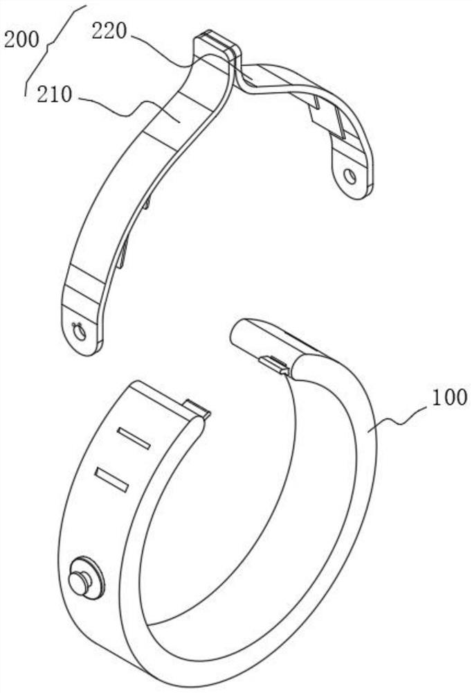
[0057] Considering that the heating ring 110 is bonded with the rough surface belt body 210 and the hook surface belt body 220, the space at the opening is reduced, and even the heating ring 110 will be closed, leaving little space for the needle to penetrate. For this reason, this embodiment discloses another working mode of the connecting mechanism 200, which mainly rotates and drives the heating ring 110 to tilt to form a cavity for needle insertion. Please refer to Figure 4 As shown, both the rough surface belt body 210 and the hook surface belt body 220 include a connecting part 200A, a force receiving part 200B and a hard part 200C, wherein:

[0058] The connection part 200A and the hard part 200C are located at both ends of the force receiving part 200B, the inner side surface of the connection part 200A of the rough surface belt body 210 is a rough surface, and the inner side surface of the connection part 200A of the hook surface belt body 220 is a hook surface;

[0...

Embodiment 3

[0064] Considering that disinfection needs to be carried out before sticking the needle, in order to utilize the opening of the heating ring 110, please refer to Figure 6 and Figure 7 As shown, a support plate 112 is provided at one end of the opening of the heating ring 110, and a bonding mechanism 300 is provided between the two support plates 112. Please refer to Figure 5 As shown, the bonding mechanism 300 includes an adhesive tape 310, the bottom of the middle part of the adhesive tape 310 is provided with a hot-melt interlayer 320, and an airtight alcohol chamber 330 is formed between the hot-melt interlayer 320 and the adhesive tape 310, the alcohol chamber 330 is pre-filled with disinfectant alcohol, and the bottom of the hot-melt interlayer 320 is provided with cotton 340 .

[0065] working principle:

[0066] After the heating ring 110 is placed on the arm, the adhesive tape 310 is bonded on the support plate 112. After the rough surface belt body 210 and the ho...


PUM


Abstract

The invention relates to blood collection equipment, in particular to blood collection equipment for promoting blood circulation based on annular heating. The device comprises a heating mechanism, the heating mechanism comprises a heating ring with an opening and a heating body group, the heating body group is arranged along the path of the heating ring, the heating body group comprises a fixed heating body and polycondensation heating bodies, and the polycondensation heating bodies are symmetrically arranged in a semicircle where the opening of the heating ring is located. A condensation polymerization groove is formed in the position, corresponding to the condensation polymerization heating body, in the heating ring, and the fixed heating body is fixedly arranged in the semicircle, opposite to the opening, of the heating ring. When the hair surface belt body and the hook surface belt body are bonded, the polycondensation heating body is stressed to move in the polycondensation groove so as to achieve the purpose that the polycondensation heating body gathers towards the opening, in this way, an arm can be pressed, one position can be heated in a concentrated mode, the arm can be rapidly heated in the cold environment, and the use effect is good. Therefore, skin looseness is guaranteed, and a blood sampling needle can be inserted into the blood sampling needle conveniently.

Description

technical field [0001] The present invention relates to a blood collection device, in particular to a blood collection device that promotes blood circulation based on annular heating. Background technique [0002] With the increase of people's awareness of blood donation, mobile blood donation stations are set up in many places in the society. The general blood donation stations use needles and needle tubes to make blood flow into the blood bag. The blood flow rate in the hospital is slow, which will affect the speed of blood collection, especially in blood donation stations. If the blood collection is slow, there will be long queues, which will undoubtedly cause unnecessary troubles for blood donors. [0003] In the existing technology, a heating body, such as a heating wire, is usually installed in the wristband, and then the wristband is worn on the arm to promote blood flow through heating, but it does not take into account that the skin is relatively tight in a cold env...

Claims


Application Information

Patent Timeline
IPC IPC(8): A61F7/00A61B17/132A61M35/00
CPCA61F7/007A61B17/1322A61M35/10A61F2007/0029A61F2007/0071
Inventor 孙岩王海燕高洪臣
Owner JILIN UNIV FIRST HOSPITAL
Why Eureka
Try Eureka