
Thrust washer

A technology of thrust washers and inner rings, applied to mechanical equipment, connecting components, etc., can solve problems such as time-consuming and labor-intensive, cumbersome and labor-intensive work processes, and affect work efficiency, and achieve the effects of convenient operation, increased automation, and reduced labor intensity

Pending Publication Date: 2022-04-19
严永存
View PDF0 Cites 0 Cited by
  • Summary
  • Abstract
  • Description
  • Claims
  • Application Information

AI Technical Summary

Problems solved by technology

[0003] Since the thrust washer is installed on the lower part of the steel wire washer for the shaft and the upper end of the thrust washer is engaged with the steel wire retaining ring for the shaft, the staff needs to smash the thrust washer downwards to separate it from the steel wire retaining ring for the shaft, and then The thrust washer can only be removed after the steel wire retaining ring for the shaft is removed; when installing, the thrust washer must be installed on the shaft first, then the steel wire retaining ring for the shaft should be installed on the shaft, and then the thrust washer should be knocked upwards , so that it is clamped on the steel wire retaining ring for the shaft. The whole working process is cumbersome and laborious, which seriously affects the work efficiency.
[0004] Although the existing technology can disassemble and assemble the thrust washer, the process is very time-consuming and labor-intensive, which affects work efficiency

Method used


Image

  • Thrust washer
  • Thrust washer
  • Thrust washer

Examples


Embodiment 1

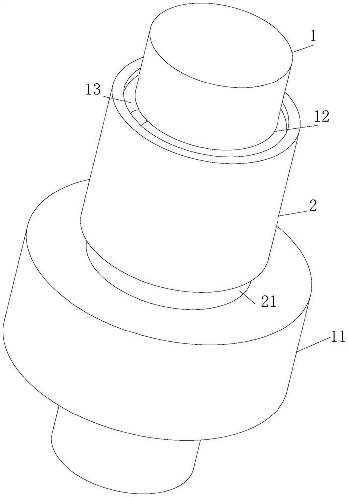
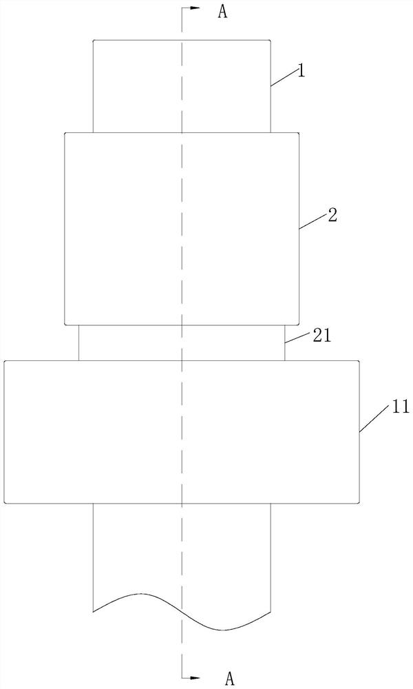
[0033] A thrust washer comprising:

[0034] Inner ring 21, the inner ring 21 is in the shape of an annular plate, the inner diameter of the inner ring 21 is equal to the outer diameter of the spline shaft 1, and the outer diameter of the inner ring 21 is not smaller than the outer diameter of the installed axial wire retaining ring;

[0035] Outer ring 2, the outer ring 2 is in the shape of an annular plate, the inner diameter of the outer ring 2 is not smaller than the outer diameter of the installed axial steel wire retaining ring, and the inner wall of the outer ring 2 is in contact with the outer wall of the inner ring 21 connect;

[0036] During work, the thrust washer of the prior art is installed on the lower part of the steel wire washer for the shaft and the upper end of the thrust washer is clamped with the steel wire retaining ring 13 for the shaft. The steel wire retaining ring 13 is disengaged, and then the shaft steel wire retaining ring 13 is removed, and then ...

Embodiment 2

[0041] Compared with embodiment 1, the difference is:

[0042] In this embodiment, the outer ring 2 and the inner ring 21 are screwed 24 .

[0043] When working, the inner wall of the outer ring 2 and the outer wall of the inner ring 21 are connected by threads. When the worker removes the steel wire retaining ring 13 for the shaft, he only needs to rotate the outer ring 2 so that the outer ring 2 moves downward relative to the inner ring 21. It has the advantages of simple structure, reliable connection, convenient assembly and disassembly, etc.

Embodiment 3

[0045] Compared with embodiment 1, the difference is:

[0046] In this embodiment, the axial position between the inner ring 21 and the outer ring 2 is connected by a tension spring 22 .

[0047] When working, the staff moves the outer ring 2 downwards to expose the steel wire retaining ring 13 for the shaft. When loosening, the tension spring 22 makes the outer ring 2 rewrap the steel wire retaining ring 13 for the shaft, thereby facilitating the alignment of the steel wire washer for the shaft. It can be disassembled, and at the same time, it will play a role in slowing down the vibration when it is subjected to axial force.


PUM


Abstract

The invention relates to the technical field of thrust washers, in particular to a thrust washer which comprises an inner ring, the inner ring is in an annular plate shape, the inner diameter of the inner ring is equal to the outer diameter of a spline shaft, and the outer diameter of the inner ring is not smaller than the outer diameter of an installed axial steel wire check ring; the outer ring is in an annular plate shape, the inner diameter of the outer ring is not smaller than the outer diameter of the installed axial steel wire check ring, and the inner wall of the outer ring is connected with the outer wall of the inner ring; through sliding connection between the outer ring and the inner ring, the outer ring moves up and down relative to the inner ring of the thrust washer, disassembly and assembly of the steel cable baffle ring for the shaft are greatly improved, and the steel cable baffle ring for the shaft has the advantages of being efficient, convenient to operate, economical and practical; by means of the lever structure, the power arm is larger than the resisting arm to form a labor-saving lever, a worker applies certain force to the blocking piece through the labor-saving lever, so that the steel wire check ring for the shaft is opened, and the labor intensity of the worker for disassembling the thrust washer is relieved.

Description

technical field [0001] The invention relates to the technical field of thrust washers, in particular to a thrust washer. Background technique [0002] A thrust washer is an annular plate or two semi-annular plates usually used with radial sliding bearings to bear axial loads, and is usually used in mechanical devices such as clutch devices, transmissions, gear mechanisms or compressors, so that it can Withstand the axial force and prolong the service life of the mechanical device. [0003] Since the thrust washer is installed on the lower part of the steel wire washer for the shaft and the upper end of the thrust washer is engaged with the steel wire retaining ring for the shaft, the staff needs to smash the thrust washer downwards to separate it from the steel wire retaining ring for the shaft, and then The thrust washer can only be removed after the steel wire retaining ring for the shaft is removed; when installing, the thrust washer must be installed on the shaft first,...

Claims


Application Information

Patent Timeline
IPC IPC(8): F16B21/10F16B21/18
CPCF16B21/10F16B21/186
Inventor 严永存于祥
Owner 严永存
Features
  • Generate Ideas
  • Intellectual Property
  • Life Sciences
  • Materials
  • Tech Scout
  • Unparalleled Data Quality
  • Higher Quality Content
  • 60% Fewer Hallucinations
Learn More