Test supporting device

A technology of supporting devices and supporting rods, which is applied in the direction of measuring device shells, testing dielectric strength, etc., can solve problems such as safety and hidden dangers, and achieve the effect of ensuring a safe distance and solving hidden safety hazards

Pending Publication Date: 2022-04-19
CRRC QINGDAO SIFANG CO LTD
View PDF0 Cites 0 Cited by
  • Summary
  • Abstract
  • Description
  • Claims
  • Application Information

AI Technical Summary

Problems solved by technology

[0003] The main purpose of the present invention is to provide a test support device to solve th

Method used


Image

  • Test supporting device

Examples


Example Embodiment

[0019] It should be noted that, in the absence of conflict, the embodiments in the present application and the features in the embodiments may be combined with each other. The present invention will be described in detail below with reference to the accompanying drawings and in conjunction with an embodiment.

[0020] In order to solve the problem of potential safety hazards in the track vehicle in the prior art when conducting UHV tests, the present invention provides a test support device.
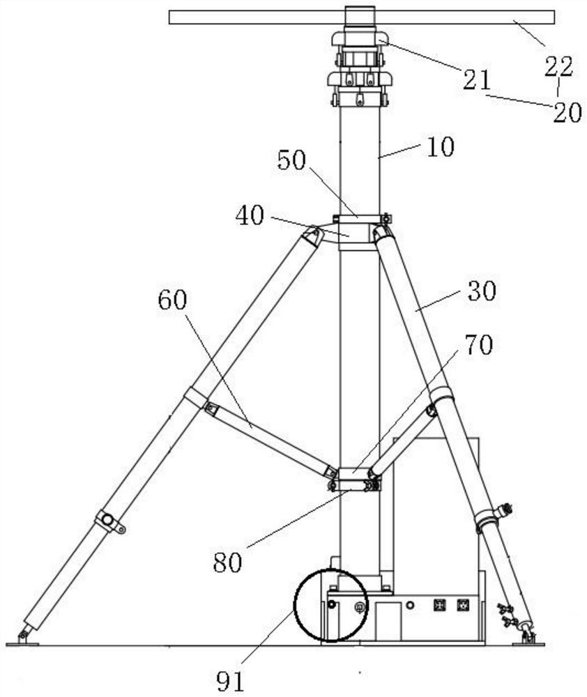
[0021] Please refer to Figure 1 , a test support device, the support device is provided between the pressure-resistant press and the car body, the support device comprises a pole assembly 10 and a turntable assembly 20, the turntable assembly 20 may be rotated to be disposed on the top of the pole assembly 10, wherein the turntable assembly 20 is provided with a card line part, the card line part is used to fix the cable.

[0022] The support device of the present invention is mainly used i...


PUM


Abstract

The invention provides a test supporting device, which is arranged between a pressure-resistant machine and a vehicle body, and comprises a vertical rod assembly, the rotating disc assembly is rotatably arranged at the top of the vertical rod assembly, and a wire clamping part is arranged on the rotating disc assembly and used for fixing a cable. According to the test supporting device, the problem that potential safety hazards exist when an extra-high voltage test is carried out on a rail vehicle in the prior art is solved.

Description

technical field [0001] The invention relates to the technical field of rail vehicle testing, in particular to a testing support device. Background technique [0002] When conducting UHV tests on rail vehicles, it is necessary to connect the EMU UHV power supply cable to the interface on the top of the vehicle. Since the cable is soft, it is easy to contact the ground, the side and the top of the car body, posing a safety hazard. Contents of the invention [0003] The main purpose of the present invention is to provide a test support device to solve the problem of potential safety hazards in the UHV test of rail vehicles in the prior art. [0004] In order to achieve the above object, according to one aspect of the present invention, a test support device is provided. The support device is arranged between the pressure-resistant machine and the vehicle body. The support device includes: a vertical rod assembly; a turntable assembly, and the turntable assembly is rotatably a...

Claims


Application Information

Patent Timeline
IPC IPC(8): G01R1/04G01R31/12
CPCG01R1/04G01R31/12
Inventor 刘真李伟郭欣邴晨阳徐晟航张超胡雪峰
Owner CRRC QINGDAO SIFANG CO LTD
Why Eureka
Try Eureka