
Eye movement tracking device

A technology of eye tracking and eye position, applied in glasses/goggles, acquisition/recognition of eyes, instruments, etc., can solve problems such as high energy consumption and high complexity

Pending Publication Date: 2022-04-22
ROBERT BOSCH GMBH +1
View PDF6 Cites 0 Cited by
  • Summary
  • Abstract
  • Description
  • Claims
  • Application Information

AI Technical Summary

Problems solved by technology

All these systems are typically of high complexity and energy consumption, often with limited temporal resolution

Method used


Image

  • Eye movement tracking device
  • Eye movement tracking device
  • Eye movement tracking device

Examples


Embodiment Construction

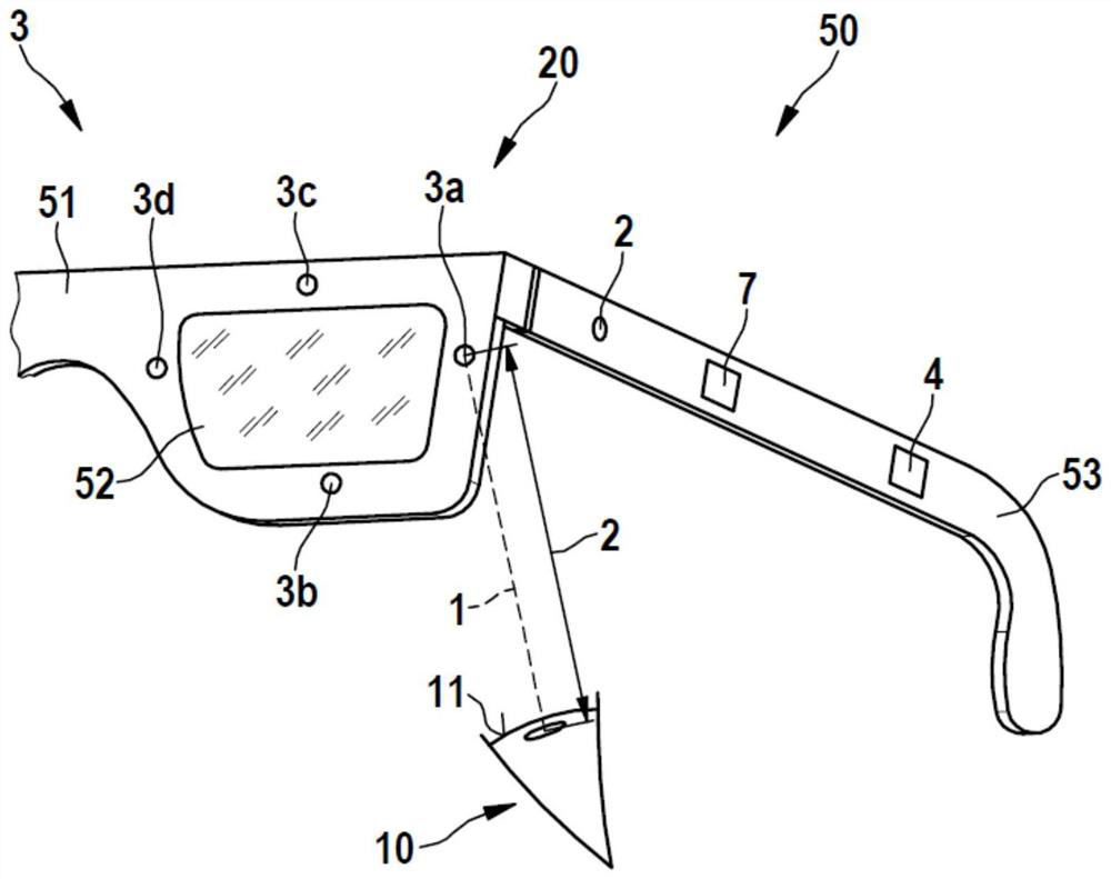
[0043] figure 1 A simplified schematic diagram of a pair of smart glasses 50 according to a first embodiment of the invention is shown. The smart glasses 50 include lenses 52 , frames 51 in which the lenses 52 are accommodated, and temples 53 for holding the smart glasses 50 on a user's head. Therefore, the smart glasses 50 are set to be worn on the user's head.

[0044] The smart glasses 50 comprise an eye-tracking device 20 by means of which the gaze direction of the user's eyes 10 can be determined and tracked. For this purpose, the eye-tracking device 20 comprises a camera 2, a laser velocimeter 3 and a control device 4 arranged to operate the camera 2 and the laser velocimeter 3 to carry out a suitable program for determining and tracking the gaze direction of the eye 10 .

[0045] The control device 4 is arranged in the smart temple 53 to achieve a compact and ergonomic design of the smart glasses 50 . Furthermore, a power source (not shown), such as a rechargeable b...


PUM


Abstract

The invention relates to an eye movement tracking device (20) comprising: a camera (2) configured to take an image of an eye (10) at a first scan rate; a laser velocimeter (3) configured to capture an eye velocity of the movement of the eye (10) at a second scanning rate by means of a laser Doppler velocimeter; and a control device (4) configured to determine an absolute eye position based on the image and to track a gaze direction of the eye (10) based on the absolute eye position and the eye speed.

Description

technical field [0001] The present invention relates to an eye tracking device, smart glasses and a method for eye tracking of an eye. Background technique [0002] Eye tracking is known for determining eye movement and estimating gaze direction. Known systems are based on acquiring information about the position of the eye using camera-based systems or electrical or electromagnetic sensors in the eye area. Furthermore, scanning laser systems are known, for example which use a micromirror to scan the laser spot across the eye. All these systems are generally of high complexity and energy consumption, often with limited temporal resolution. Contents of the invention [0003] On the contrary, the eye-tracking device according to the invention with the features of claim 1 is characterized by the incorporation of a particularly energy-efficient, cost-effective and temporally high-resolution eye-tracking option. This is achieved through an eye-tracking setup that includes ca...

Claims


Application Information

Patent Timeline
Patent Type & Authority Applications(China)
IPC IPC(8): G02B27/00G02C11/00
CPCG02B27/0093G02C11/10G06F3/013G02B27/0172G02B2027/0178G06V40/193G06V40/19
Inventor 安德烈亚斯·彼得森托马斯·亚历山大·施莱布施汉斯·斯普鲁伊特约琴·赫尔米格
Owner ROBERT BOSCH GMBH
Learn More