Coin retention prevention device and coin lifting device for preventing coin retention

A coin and driving device technology, which is applied in the direction of accepting coins, handling coins or valuable banknotes, instruments, etc., can solve the problems of affecting customer experience, increasing maintenance costs, and coin retention, so as to achieve good customer experience and reduce maintenance The effect of cost and easy maintenance

Pending Publication Date: 2022-04-22
NANJING PANDA ELECTRONICS +1
View PDF0 Cites 0 Cited by
  • Summary
  • Abstract
  • Description
  • Claims
  • Application Information

AI Technical Summary

Problems solved by technology

In the prior art, the change opening is too low, which is not ergonomic. In addition, coins often stay in the channel, or coins are rolled back and forth in the coin storage, resulting in the coins not being lifted out within the specified change time.
These issues not only affect customer experience, but also increase maintenance costs

Method used


Image

  • Coin retention prevention device and coin lifting device for preventing coin retention
  • Coin retention prevention device and coin lifting device for preventing coin retention
  • Coin retention prevention device and coin lifting device for preventing coin retention

Examples


Embodiment 1

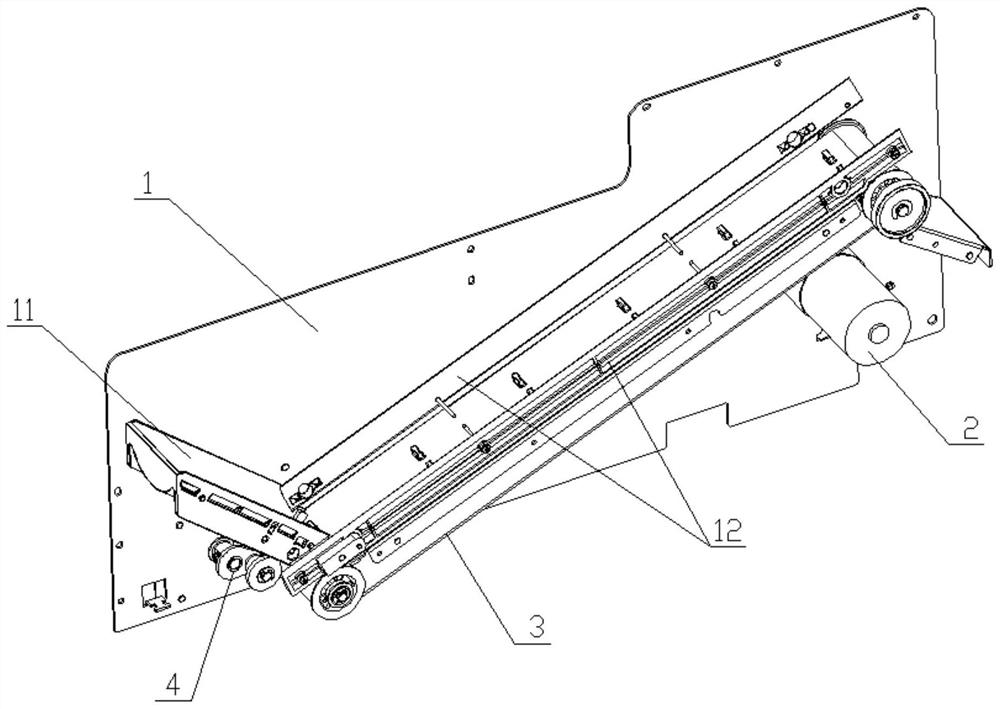
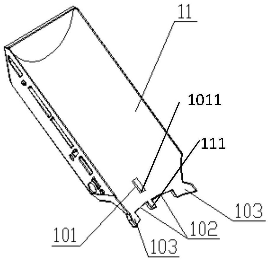
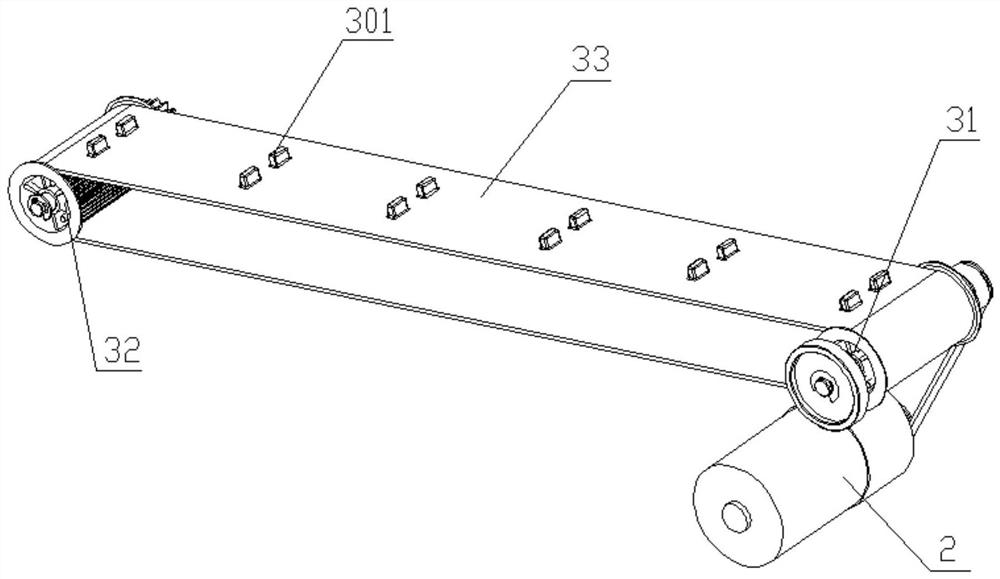
[0033] Such as figure 1 As shown, a device for preventing coin retention in this embodiment includes a frame 1, a conveying device 3 and a coin shifting device 4, and a chute 11 and a baffle 12 are fixedly installed in the frame 1, and the chute 11 is arranged obliquely, and the horizontal plane The included angle is an acute angle, and the bottom of the chute 11 is in contact with the conveyor belt 33, as figure 2 As shown, the front surface of the chute 11 forms a circular arc depression to the rear, the chute 11 is provided with a notch 101, the distance from the bottom 1011 of the notch 101 to the bottom 111 of the chute 11 is less than the diameter of the coin, the bottom of the chute 11 is provided with a groove 102, and the groove 102 The length is smaller than the diameter of the coin. In this embodiment, two grooves 102 are arranged at the bottom of the chute 11, and the notch 101 is arranged directly above the two grooves 102, for the toggle rod 43 to toggle between...

Embodiment 2

[0040] Such as Figure 9 and Figure 10 As shown, a coin lifting device for preventing coin retention in this embodiment includes a frame 1, a transfer device 3 and a coin shifting device 4, the frame 1 is an L-shaped bracket, and the L-shaped bracket is provided with an inspection port 7 and a pair of The sensor 8 and the inspection port 7 can observe the operating status of the coin shifting device 4 and the conveying device 3, and the sensor 8 can detect whether there are coins remaining at the connection between the coin shifting device 4 and the conveying device 3 and feed back the information to the host computer. A chute 11 and a baffle plate 12 are fixedly installed in the frame 1, the chute 11 is arranged obliquely, and the included angle with the horizontal plane is an acute angle, and the bottom of the chute 11 is in contact with the conveyor belt 33, as Figure 11 and Figure 12 As shown, the front surface of the chute 11 forms a circular arc recess toward the re...


PUM


Abstract

The invention discloses a coin retention prevention device and a coin lifting device for preventing coin retention, each of the coin retention prevention device and the coin retention prevention device comprises a conveying belt, a chute fixedly arranged at the input end of the conveying belt and a coin shifting device, the coin shifting device comprises a shifting rod driving device and a shifting rod which are arranged behind the chute, the chute is provided with a notch, one end of the shifting rod extends out of the notch, and the other end of the shifting rod extends out of the notch. The poke rod driving device drives the poke rod to stretch out and retract back and forth in the notch in a reciprocating mode. A conveying belt of the coin lifting device comprises a driving conveying belt and a driven conveying belt, the driving conveying belt comprises a transverse moving section moving in the inclined direction and a lifting section moving in the vertical direction, the lifting section of the driving conveying belt is attached to the driven conveying belt, and the belt of the attaching face is in a zigzag Z-shaped trend. The poke rod which stretches out and withdraws back in the notch in a reciprocating mode pokes coins detained on the sliding groove or pokes coins rolling between the sliding groove and the conveying belt, the problem of detained coins when the coins are output is solved, and the device is simple in structure and convenient to maintain.

Description

technical field [0001] The invention relates to an auxiliary device for coin transmission, in particular to a device for preventing coin retention and a coin lifting device for preventing coin retention. Background technique [0002] A coin temporary storage module and a coin transfer mechanism are usually provided in a coin processing device, wherein the coin temporary storage module includes a coin replenishment box and a recirculation change box, and the coin transfer mechanism includes a driving roller, a driven roller and a belt. The coin temporary storage module is located above the coin conveying mechanism. When conveying coins, the coins in the temporary storage module will slide down to the belt through the chute or directly drop on the belt, and then the coins will be conveyed to the coin outlet for The user takes it away. In the prior art, there is a problem that individual coins can get stuck on the chute or the belt, causing disputes in the transaction. [000...

Claims


Application Information

Patent Timeline
Patent Type & Authority Applications(China)
IPC IPC(8): G07D11/10G07D11/14G07D11/18
CPCG07D11/10G07D11/14G07D11/18
Inventor 焦科杰陆斌胡凯王浩王松松潘超
Owner NANJING PANDA ELECTRONICS
Why Eureka
Try Eureka