Steel pipe derusting and paint spraying device for building

A technology for construction and steel pipes, applied in spraying devices, grinding drive devices, manufacturing tools, etc., can solve the problems of low efficiency and heavy labor, and achieve the effect of fast and simple operation, less trouble, and easy handling of steel pipes

Active Publication Date: 2022-04-26
佛山绿水清源管业科技有限公司
View PDF6 Cites 1 Cited by
  • Summary
  • Abstract
  • Description
  • Claims
  • Application Information

AI Technical Summary

Problems solved by technology

[0004] In order to overcome the labor-intensive and low efficiency of manual derusting and painting of steel pipes, and at the same time, the method of spraying and painting with paint spray cans will easily cause additional paint to be sprayed into the surrounding environment. The technical problem of the present invention is : Provide a kind of high-efficiency, without too many manual operations, and the extra paint will not be randomly sprayed and left around the steel pipe derusting paint spraying device for construction

Method used


Image

  • Steel pipe derusting and paint spraying device for building
  • Steel pipe derusting and paint spraying device for building
  • Steel pipe derusting and paint spraying device for building

Examples


Embodiment 1

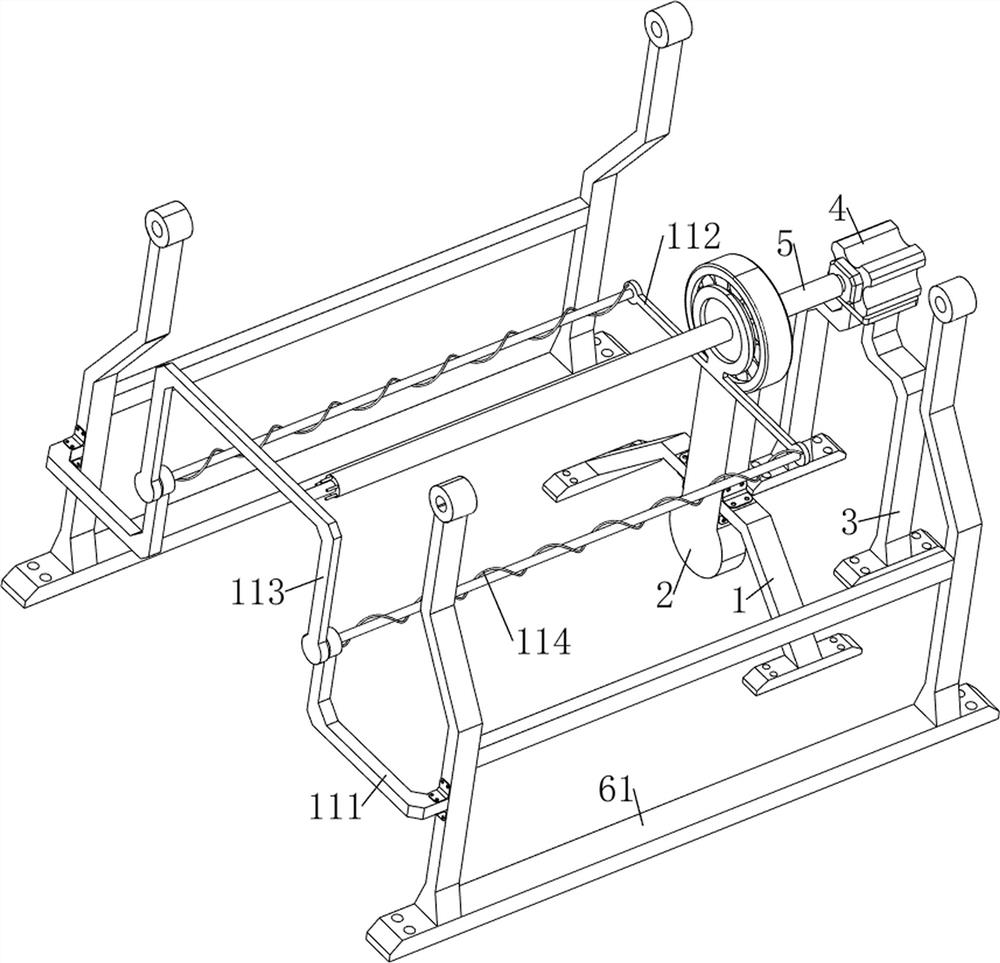
[0037] A steel pipe derusting paint spraying device for construction, such as figure 1 , figure 2 , image 3 , Figure 4 , Figure 5 , Figure 6 , Figure 7 , Figure 14 and Figure 15 As shown, it includes a support frame 1, a first connecting rod 2, a first fixed frame 3, a motor 4, a rotating rod 5, a derusting mechanism 11, a moving mechanism 6 and a spraying mechanism 7, and the top of the first fixed frame 3 is provided with a motor 4. The output shaft of the motor 4 is provided with a rotating rod 5 for covering the steel pipe. The support frame 1 is placed symmetrically on the left side of the first fixed frame 3, and the first connecting rod 2 is connected between the two support frames 1. , the rotating rod 5 is connected to the first connecting rod 2 in a rotational manner, and a moving mechanism 6 is placed on the outside of the two support frames 1. The moving mechanism 6 cooperates with the rotating rod 5, and the moving mechanism 6 is provided with a ste...

Embodiment 2

[0043] On the basis of Example 1, such as figure 1 , Figure 8 , Figure 9 , Figure 10 , Figure 11 , Figure 12 and Figure 13 As shown, a limit mechanism 8 is also included, and the limit mechanism 8 includes a slide rail 81, a second connecting rod 82, a first spring 83, a first support rod 84 and a limit block 85, which are located at the two second fixed frames 61 A slide rail 81 is placed on the left side of the inner side, and the middle part of the slide rail 81 has a card slot. The second connecting rod 82 is welded in the slide rail 81, and the first supporting rod 84 is movable on the second connecting rod 82. The first support rod 84 cooperates with the draw-in groove, the first spring 83 is sleeved on the second connecting rod 82, the left end of the first spring 83 links to each other with the slide rail 81, the first support rod 84 cooperates with the right end of the first spring 83, and the first support The upper side of the bar 84 is rotatably provide...


PUM


Abstract

The invention relates to a derusting and paint spraying device, in particular to a derusting and paint spraying device for a steel pipe for a building. The derusting and spraying device for the steel pipe for the building is high in efficiency and does not need excessive manual operation, and extra paint cannot be sprayed and left around at will. A steel pipe derusting and paint spraying device for a building comprises supporting frames, a first connecting rod, a first fixing frame, a motor, a rotating rod, a moving mechanism and the like, the motor is arranged at the top of the first fixing frame, the rotating rod is arranged on an output shaft of the motor, the supporting frames are symmetrically placed on the left side of the first fixing frame front and back, and the first connecting rod is connected between the two supporting frames; the rotating rod is rotationally connected with the first connecting rod, and a moving mechanism is placed on the outer sides of the two supporting frames. The rotating rod is sleeved with the steel pipe, the motor works to drive the rotating rod and the steel pipe to rotate, paint is evenly sprayed to the outer wall of the steel pipe, operation can be automatically conducted, and excessive manual operation is not needed.

Description

technical field [0001] The invention relates to a derusting and painting device, in particular to a derusting and painting device for steel pipes used in construction. Background technique [0002] Steel pipe is one of the most commonly used hardware accessories in various buildings. The paint layer on the outer wall of the steel pipe is prone to paint peeling and rust during long-term use. Generally, rust removal and refurbishment will be carried out on severely rusted steel pipes, which can improve Its corrosion resistance, anti-rust ability and aesthetics, etc., the general rust removal spraying method is to manually scrape off the rust on the severely rusted area of ​​the steel pipe, and then use the paint spray can to clean the outer wall of the steel pipe after rust removal. Painting, such a manual operation method affects work efficiency and is labor-intensive, and the method of painting with a hand-held paint spray can easily leads to uneven paint on the outer wall o...

Claims


Application Information

Patent Timeline
Patent Type & Authority Applications(China)
IPC IPC(8): B05B13/02B05B13/04B05B14/00B05B15/68B24B27/033B24B5/36B24B5/35B24B41/04B24B41/06B24B47/20
CPCB05B13/0228B05B13/041B05B14/00B05B15/68B24B27/033B24B5/36B24B5/35B24B41/04B24B41/067B24B47/20Y02P70/10
Inventor 邓世杰
Owner 佛山绿水清源管业科技有限公司
Why Eureka
Try Eureka