Elastic force driving test bench and use method thereof

A test bench and elastic force technology, applied in the direction of applying stable tension/pressure to test material strength, testing of mechanical components, testing of machine/structural components, etc., can solve equipment construction costs, use costs, high maintenance costs, and equipment High cost, use cost and maintenance cost, unable to simulate the high-speed loading process, etc., to achieve the effect of low maintenance cost and use cost, simple structure and increased speed

Active Publication Date: 2022-04-26
HUNAN UNIV
View PDF6 Cites 0 Cited by
  • Summary
  • Abstract
  • Description
  • Claims
  • Application Information

AI Technical Summary

Problems solved by technology

[0003] Existing rotary loading devices and equipment, such as motor-driven rotary loading devices, generally achieve rotary loading by controlling the driving motor; if the angular velocity changes greatly in a short period of time and the accompanying torque changes greatly, very precise control is required system, and consume a lot of energy during use; the cost of such equipment, use cost and maintenance cost are generally high, which undoubtedly pushes up the cost of the product, especially for a small number of products that must be produced and tested. class device component
[0004] Existing linear loading devices and equipment, such as hydraulic actuators, are expensive, costing tens of millions; and consume a lot of energy during use, resulting in high maintenance costs; in addition, the peak speed of such equipment is generally relatively high Small, many of which do not exceed 1m / s; and for impact devices with instantaneous high-speed loading such as Hopkinson rods, it is difficult to achieve high-speed and long-term loading, and it is impossible to simulate the high-speed loading process for a period of time, and there is also equipment construction cost , Use cost, high maintenance cost

Method used


Image

  • Elastic force driving test bench and use method thereof
  • Elastic force driving test bench and use method thereof

Examples


Embodiment 1

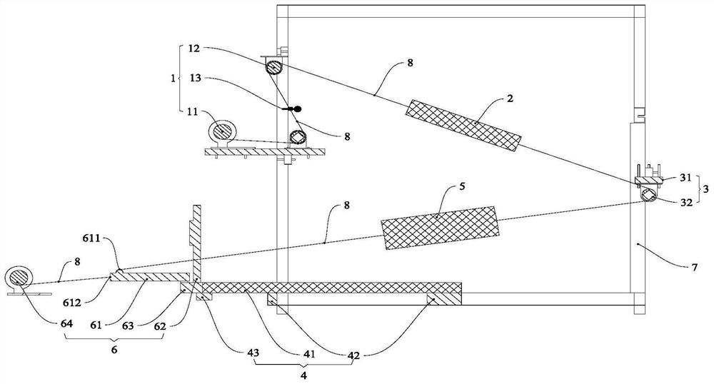
[0053] Such as figure 1 As shown, an elastic drive test bench includes a loading device 1, an elastic driving device 2, a vertical adjustment device 3, a horizontal adjustment device 4, a pulley block 5, a specimen installation device 6, a frame 7 and a connecting rope 8, and the loading device 1. Both the vertical adjustment device 3 and the horizontal adjustment device 4 are installed on the frame 7 . specific:

[0054] The loading device 1 includes a loader 11 and a locking device 13 , and the loader 11 is connected to the elastic driving device 2 through a connecting rope 8 . The loader 11 is used to apply load to the elastic driving device 2 , and the locking device 13 is used to lock the load applied to the elastic driving device 2 .

[0055] As a preferred implementation, the loader 11 can be a winch with a simple structure and low price, or other driving and loading devices, the locking device 13 can be a detachable connection structure such as a buckle or a hoop, an...

Embodiment 2

[0064] A method for using an elastic force-driven test bench, using a kind of elastic force-driven test bench as in embodiment 1 to carry out rotational loading, comprising the following steps:

[0065] Step 1: According to the test requirements, determine the required output load of the loading device 1;

[0066] Step 2: Select the appropriate loader 11, elastic driving device 2, pulley block 5, etc. according to the required output load;

[0067] Step 3: Install and fix the frame 7;

[0068] Step 4: Install the loading device 1, the vertical adjustment device 3, and the horizontal adjustment device 4 on the frame 7, adjust the position of the test piece 61 and install it on the horizontal adjustment device 4; adjust the installation of the vertical adjustment device 3 on the frame 7 position, so that the reversing wheel 32 and the test piece 61 are located at different heights;

[0069] Step 5: Connect the loading device 1, the elastic driving device 2, the vertical adjust...

Embodiment 3

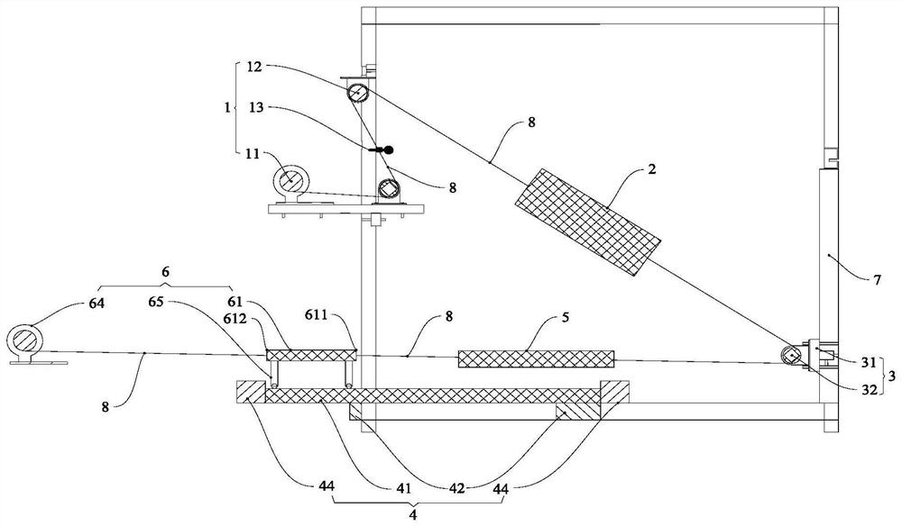
[0078] Based on the elastic drive test bench described in Example 1, in the linear loading mode, some components have changed, specifically, as figure 2 Shown:

[0079] Remove the rotation limiting device 62, the test piece mounting base 63 and the recovery loading device 64, and adjust the installation position of the vertical adjustment device 3 on the frame 7 so that the reversing wheel 32 and the test piece 61 are at the same height. And the loading connection point 611 of the test piece 61 connected to the reversing wheel 32 and the recovery connection point 612 connected to the recovery loading device 64 are located at opposite ends, therefore, the test piece 61 can slide or roll along the slide rail 41, and through structural design , so that the coefficient of friction between the test piece 61 and the slide rail 41 is less than or equal to 0.01.

[0080] As a preferred embodiment, the test piece 61 is provided with a test piece installation trolley 62 or other rolla...


PUM


Abstract

The invention discloses an elastic force driving test bench and a use method thereof, the test bench comprises a loading device, an elastic force driving device, a vertical adjusting device, a horizontal adjusting device, a test piece installation device and a frame, and the loading device, the vertical adjusting device and the horizontal adjusting device are all installed on the frame; the loading device comprises a loader and a locking device, the elastic force driving device comprises a spring, the loader is used for applying a load to the spring, the locking device is used for locking the load of the spring, the vertical adjusting device comprises a sliding adjusting locking block and a reversing wheel, and the sliding adjusting locking block can drive the reversing wheel to slide up and down and lock the position. The horizontal adjusting device is provided with a sliding rail, the test piece mounting device comprises a test piece and a recovery loading device, and the test piece is placed on the sliding rail; the loader is sequentially connected with the elastic force driving device, the reversing wheel and the test piece through the connecting rope, and the recovery loading device is connected with the test piece through the connecting rope and can lock or release the test piece.

Description

technical field [0001] The invention relates to a loading test device, in particular to an elastic drive test stand and its application method. Background technique [0002] Before all kinds of engineering equipment and products are put into use, many of them need to be tested for rotational loading and linear loading. [0003] Existing rotary loading devices and equipment, such as motor-driven rotary loading devices, generally achieve rotary loading by controlling the driving motor; if the angular velocity changes greatly in a short period of time and the accompanying torque changes greatly, very precise control is required system, and consume a lot of energy during use; the cost of such equipment, use cost and maintenance cost are generally high, which undoubtedly pushes up the cost of the product, especially for a small number of products that must be produced and tested. class device components. [0004] Existing linear loading devices and equipment, such as hydraulic ...

Claims


Application Information

Patent Timeline
Patent Type & Authority Applications(China)
IPC IPC(8): G01N3/02G01N3/14G01N3/26G01M13/00
CPCG01N3/02G01N3/14G01N3/26G01M13/00
Inventor 王帅张弘毅陈政清
Owner HUNAN UNIV
Why Eureka
Try Eureka