
Hydrogen centralized storage equipment for hydrogen fuel cell

A technology of fuel cells and storage equipment, applied in the field of centralized hydrogen storage equipment for hydrogen fuel cells, which can solve the problems of poor flexibility, poor practicability, and difficulty in adjusting the number of hydrogen storage bottles installed, and achieves convenient installation and disassembly, heat exchange Uniform, flexible effects

Pending Publication Date: 2022-04-29
常州德尔松压力容器有限公司
View PDF1 Cites 0 Cited by
  • Summary
  • Abstract
  • Description
  • Claims
  • Application Information

AI Technical Summary

Problems solved by technology

[0004] Although the above-mentioned existing technical solutions can realize the fixed installation of hydrogen storage bottles, the structure of the fixed base is relatively fixed. When dealing with the installation space of hydrogen fuel cell vehicles of different specifications and models, it is not easy to adjust the number of hydrogen storage bottles installed. It is also not easy to adjust the relative arrangement of multiple hydrogen storage bottles, and the flexibility of use is poor. At the same time, the heat exchange function of the fixed base is not easy to achieve the overall cooling of the hydrogen storage bottles, and the practicability is poor.

Method used


Image

  • Hydrogen centralized storage equipment for hydrogen fuel cell
  • Hydrogen centralized storage equipment for hydrogen fuel cell
  • Hydrogen centralized storage equipment for hydrogen fuel cell

Examples


Embodiment

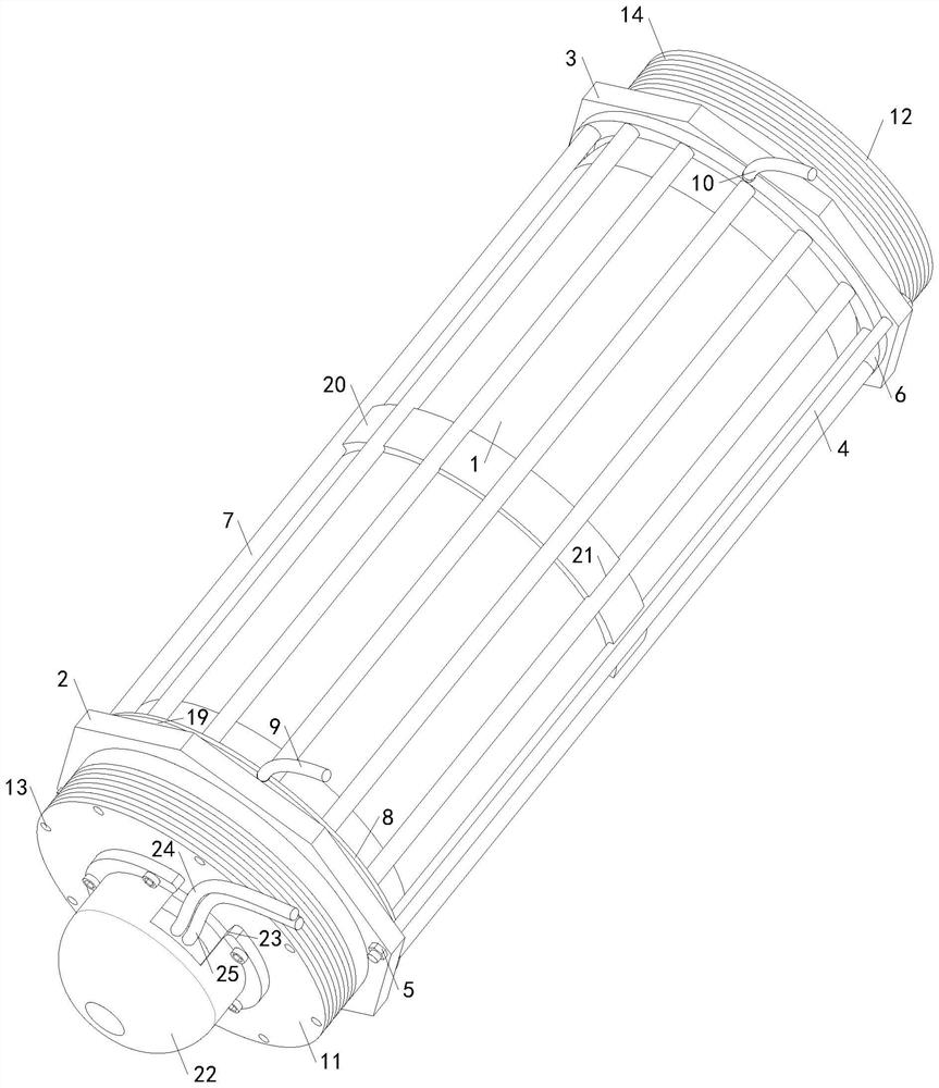
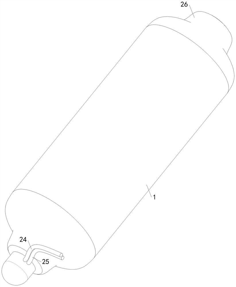
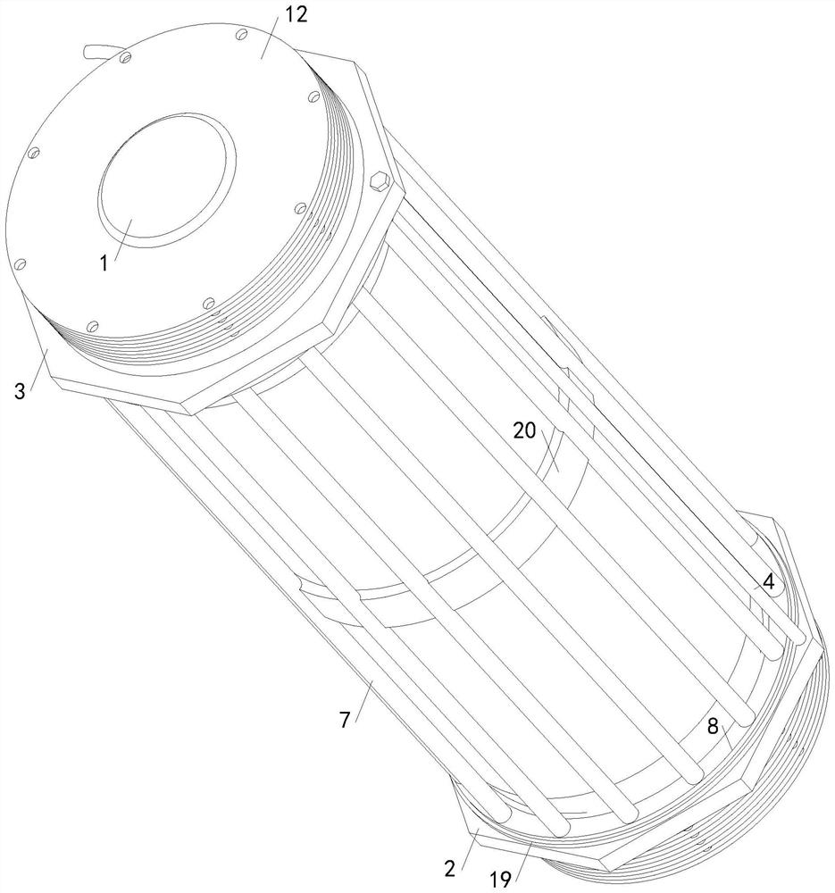
[0031] see Figure 1-6 , hydrogen centralized storage equipment for hydrogen fuel cells, including a plurality of hydrogen storage bottles 1, and also includes a plurality of mounting brackets for connecting and installing the hydrogen storage bottles 1, the mounting brackets include a front mounting prism 2 and a rear mounting prism 3, Both the front mounting edge ring 2 and the rear mounting edge ring 3 are provided with positioning holes, and the hydrogen storage bottle 1 is set in the positioning hole, and the hydrogen storage bottle 1 is provided with a gradient depression 26 matching the positioning hole, and cooperates with the positioning hole to realize storage. Clamping and positioning of the hydrogen bottle 1, a plurality of connecting rods 4 are symmetrically fixedly connected to the rear mounting rib ring 3, and compression nuts 5 are threaded on the multiple connecting rods 4, and multiple connecting rods 4 are threaded on the front mounting rib ring 2 The connec...


PUM


Abstract

The invention relates to the technical field of hydrogen centralized storage equipment, and provides hydrogen centralized storage equipment for hydrogen fuel cells, aiming at hydrogen fuel cell vehicles with different specifications and models, the hydrogen centralized storage equipment not only can realize the adjustment of the installation number of hydrogen storage bottles, but also can realize the adjustment of the relative arrangement positions of a plurality of hydrogen storage bottles, is more flexible to use, and is more uniform in heat exchange. The hydrogen storage device is relatively practical and comprises a plurality of hydrogen storage bottles and a plurality of mounting frames, each mounting frame comprises a front mounting edge ring and a rear mounting edge ring, the hydrogen storage bottles are arranged between the front mounting edge rings and the rear mounting edge rings, the rear mounting edge rings are connected with a plurality of connecting rods, the connecting rods are connected with pressing nuts, the front mounting edge rings are provided with a plurality of connecting holes, and the front mounting edge rings are provided with pressing nuts. The front mounting edge ring is connected with a collecting ring, the rear mounting edge ring is connected with a collecting ring, the collecting ring is communicated with a mounting ring through a plurality of cooling pipes, the mounting ring and the collecting ring are respectively communicated with a cooling water inlet pipe and a cooling water outlet pipe, and the front mounting edge ring and the rear mounting edge ring are respectively provided with connecting rings through a front assembling frame and a rear assembling frame.

Description

technical field [0001] The invention relates to the technical field of hydrogen centralized storage equipment, in particular to a hydrogen centralized storage equipment for hydrogen fuel cells. Background technique [0002] As we all know, hydrogen energy is a green and efficient secondary energy source, which has the characteristics of high calorific value, abundant reserves, diverse sources, wide application and multiple utilization forms. Hydrogen fuel cells use hydrogen as a chemical element to manufacture storage Energy batteries, the characteristics of hydrogen fuel cells determine that it has broad application prospects. It can be used not only in large-scale power stations for power generation and portable mobile power supplies, but also in aircraft, automobiles, and warships. The hydrogen energy industry chain includes hydrogen production, hydrogen storage and transportation. How to realize the storage of hydrogen when used as a mobile power source has become a high...

Claims


Application Information

Patent Timeline
Patent Type & Authority Applications(China)
IPC IPC(8): F17C1/00F17C13/00F17C13/08H01M8/04082
CPCF17C1/00F17C13/002F17C13/08H01M8/04201Y02E60/32Y02E60/50
Inventor 巢瑜吴广林巢建松
Owner 常州德尔松压力容器有限公司
Learn More