
Special assemblage machine for grid assembly of heat radiator

A radiator and assembly technology, which is applied in the field of radiator grille assembly assembly machine, can solve problems such as instability, inability to assemble in place, and bruises, etc., to reduce tooling costs, reduce fracturing phenomena, and improve production efficiency Improved effect

Pending Publication Date: 2018-06-29
NINGBO MINTH AUTOMOTIVE PARTS RES&DEV CO LTD
View PDF0 Cites 0 Cited by
  • Summary
  • Abstract
  • Description
  • Claims
  • Application Information

AI Technical Summary

Problems solved by technology

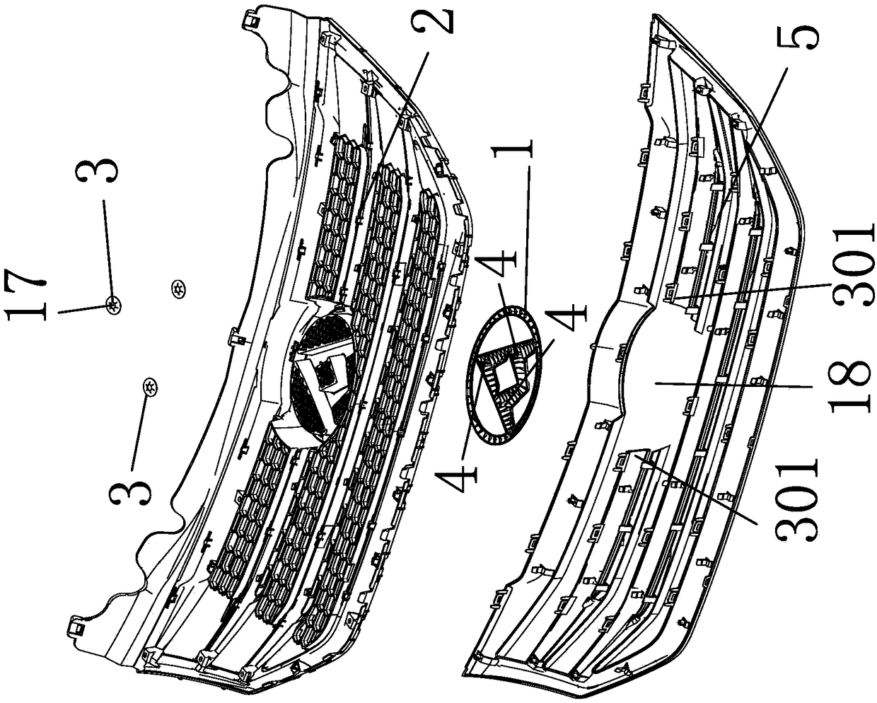
[0002] like figure 1 As shown, the radiator grille assembly generally includes three parts: the signage part 1, the outer frame part 30 and the main part 2. Here, the three parts of the signage part 1, the outer frame part 30 and the main part 2 need to be assembled during the production process. Together, the existing methods here are directly assembled manually. Since the entire assembly has about 60 jaws, the current manual assembly capacity is relatively low. Manual assembly can make about 6 products in one hour, and the assembly It is time-consuming and labor-intensive, and the claws are unstable when assembled, and cannot be assembled in place, resulting in fracturing of the claws, and it is impossible to realize 60 claws to be assembled in place at one time. Due to the unreliable positioning of the entire radiator grille assembly, it will cause Deformation, the label placing part 1 and the snap spring part 3 cannot be put in place, and the appearance of the radiator grille assembly is easy to be scratched and bruised when assembled and pressed together, and the two claws on the upper end of the outer frame part 30 are far away from the injection flow. Road, causing the two claws to be soft, the two claws cannot be snapped into the body part 2 by using an ordinary mechanism

Method used


Image

  • Special assemblage machine for grid assembly of heat radiator
  • Special assemblage machine for grid assembly of heat radiator
  • Special assemblage machine for grid assembly of heat radiator

Examples


Embodiment Construction

[0035] The following are specific embodiments of the present invention and in conjunction with the accompanying drawings, the technical solutions of the present invention are further described, but the present invention is not limited to these embodiments.

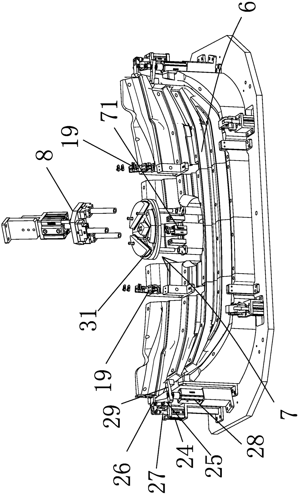
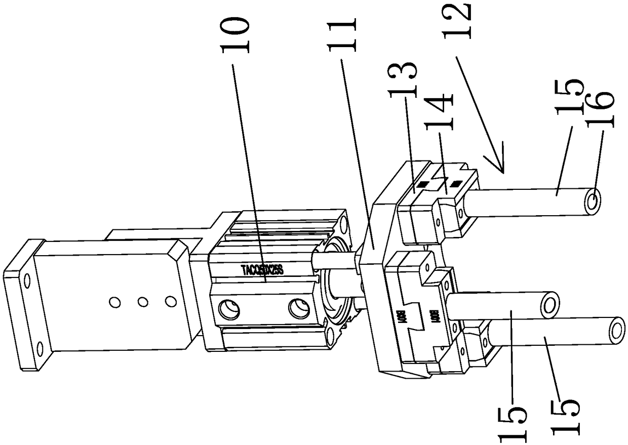
[0036] In the figure, the sign part 1; the body part 2; the spring part 3; the sleeve rod 4; the main frame 5; the main assembly stand 6; the movable support assembly 7; ; guide shaft 74; circlip pressing assembly 8; main support connection block 9; pressure rod cylinder 10; pressure rod connecting plate 11; Pressing cylinder mouth 16; snap-in cone angle 17; signage installation space 18; adsorption assembly 19; vacuum support block 20; adsorption fixing block 21; air block plug joint 22; adsorption head 23; ; Main pressing block 26; Output rod 27; Rotating cylinder 28; Rotating pressing block 29; Outer frame 30; Disconnection 301; 34; the first pressure cylinder 35; the first pressure foot 36; the pressure plane foot 37;...


PUM


Abstract

The invention belongs to the technical field of automation equipment and provides a special assemblage machine for a grid assembly of a heat radiator. A brand part is provided with a loop bar; the loop bar penetrates a body part; a snap spring part is arranged at the joint of the loop bar and the body part; an outer frame part is provided with a plurality of clamping claw parts; the body part is provided with clamping grooves which are in clamp fit with the plurality of clamping claw parts; the special assemblage machine comprises a main frame, a main assemblage jig table, a plurality of clamping claw pressing components, a brand jig table, a movable supporting component and a snap spring pressing component; and the snap spring pressing component is positioned over the brand jig table andis used for clamping the snap spring part into the loop bar so that the brand part and the body part are connected to form a whole body. The special assemblage machine provided by the invention has the advantages that the tool cost is lowered, the time is saved, relatively convenient debugging is realized, actions are reduced, parts are convenient to place, the production efficiency is also improved, the efficiency of the special assemblage machine is improved by 600 times in comparison with that of manual assemblage, press-cracking degree of the current clamping claws is reduced, assemblage can be finished at a time, the production efficiency is greatly improved, and scrapping caused by poor quality is reduced.

Description

technical field [0001] The invention belongs to the technical field of automation equipment, and in particular relates to a special machine for assembling a radiator grille assembly. Background technique [0002] like figure 1 As shown, the radiator grille assembly generally includes three parts: the signage part 1, the outer frame part 30 and the main part 2. Here, the three parts of the signage part 1, the outer frame part 30 and the main part 2 need to be assembled during the production process. Together, the existing methods here are directly assembled manually. Since the entire assembly has about 60 jaws, the current manual assembly capacity is relatively low. Manual assembly can make about 6 products in one hour, and the assembly It is time-consuming and labor-intensive, and the claws are unstable when assembled, and cannot be assembled in place, resulting in fracturing of the claws, and it is impossible to realize 60 claws to be assembled in place at one time. Due to...

Claims


Application Information

Patent Timeline
IPC IPC(8): B23P21/00
CPCB23P21/00B23P2700/10
Inventor 刘省根
Owner NINGBO MINTH AUTOMOTIVE PARTS RES&DEV CO LTD
Learn More