
Sound wave visualization interaction device

An interactive device and sound wave technology, applied in the field of teaching aids, can solve the problems of high equipment cost, lack of enthusiasm for active learning and exploration, and inability to visualize knowledge.

Pending Publication Date: 2022-04-29
TERMINUSBEIJING TECH CO LTD
View PDF0 Cites 0 Cited by
  • Summary
  • Abstract
  • Description
  • Claims
  • Application Information

AI Technical Summary

Problems solved by technology

[0002] Based on a large number of interviews and surveys, it is found that most of the young people's cognition and learning of science and physics knowledge are only in the written lesson plan teaching and test-taking learning, but they lack the cognition of the practical application of science and physics knowledge, and even less The enthusiasm of active learning and exploration; at its root, the main reason is that a lot of scientific knowledge is too abstract, and most of the accessible books are formulas and topics, which makes students unable to visualize knowledge, and then subconsciously It has buried the bane of science and physics knowledge being boring, let alone mobilizing the enthusiasm of students to actively explore and seek knowledge.
[0003] Sound wave visualization is a method of learning and researching sound wave knowledge, but it is mainly realized by high-tech devices such as intelligent hardware and computers, and mainly exists in the research or application of professional fields, and the knowledge system of these devices is complex and the cost of equipment is high. Not intended for learning and use in schools

Method used


Image

  • Sound wave visualization interaction device
  • Sound wave visualization interaction device
  • Sound wave visualization interaction device

Examples


Embodiment Construction

[0023] The technical solutions of the present invention will be clearly and completely described below in conjunction with the accompanying drawings. Apparently, the described embodiments are some of the embodiments of the present invention, but not all of them. Based on the embodiments of the present invention, all other embodiments obtained by persons of ordinary skill in the art without making creative efforts belong to the protection scope of the present invention.

[0024] In the description of the present invention, it should be noted that the terms "center", "upper", "lower", "left", "right", "vertical", "horizontal", "inner", "outer" etc. The indicated orientation or positional relationship is based on the orientation or positional relationship shown in the drawings, and is only for the convenience of describing the present invention and simplifying the description, rather than indicating or implying that the referred device or element must have a specific orientation, ...


PUM


Abstract

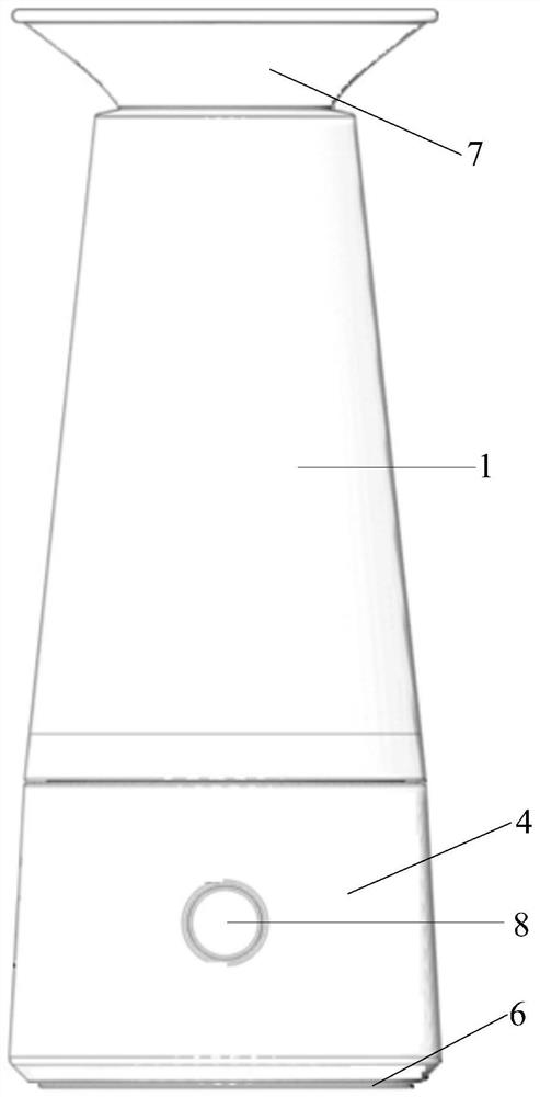
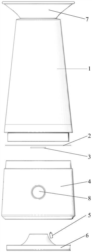
The invention relates to the technical field of teaching aids, in particular to a sound wave visualization interaction device which comprises a first cylinder, a second cylinder, a vibration part, a light reflection part and a laser emitter, the first cylinder is provided with a central cavity, a first port and a second port, the first port and the second port are communicated with the central cavity, and the first port is used for receiving a sound wave source; the vibrating piece is mounted at the second port and is suitable for vibrating under the driving of the sound wave source; the reflecting part is mounted on the vibrating part; the two ends of the second barrel are open, and the first end is installed on the second port. The laser emitter is arranged in the second cylinder, and a laser beam emitted by the laser emitter is reflected by the light reflecting piece and then is emitted out from the second end of the second cylinder. According to the structure, sound wave visualization is achieved at a low price on the basis that high-tech elements such as programming and intelligent hardware are not used, scientific knowledge is more three-dimensional and vivid, meanwhile, the interaction mode is novel, teaching through lively activities can be achieved, the learning enthusiasm of students is aroused, and the exploration ability of the students is cultivated.

Description

technical field [0001] The invention relates to the technical field of teaching aids, in particular to a sound wave visualization interaction device. Background technique [0002] Based on a large number of interviews and surveys, it is found that most of the young people's cognition and learning of science and physics knowledge are only in the written lesson plan teaching and test-taking learning, but they lack the cognition of the practical application of science and physics knowledge, and even less The enthusiasm of active learning and exploration; at its root, the main reason is that a lot of scientific knowledge is too abstract, and most of the accessible books are formulas and topics, which makes students unable to visualize knowledge, and then subconsciously It has buried the bane of science and physics knowledge being boring, let alone mobilizing the enthusiasm of students to actively explore and seek knowledge. [0003] Sound wave visualization is a method of learn...

Claims


Application Information

Patent Timeline
IPC IPC(8): G09B23/14
CPCG09B23/14
Inventor 王贝唯
Owner TERMINUSBEIJING TECH CO LTD
Learn More