A Manipulator Structure Suitable for Warped Wafer Pick-and-Place

A technology of manipulators and wafers, which is applied in sustainable manufacturing/processing, climate sustainability, and final product manufacturing. It can solve the problems of easy falling and greater need for wafer adsorption, so as to achieve reliable bonding and prevent falling. Effect

Active Publication Date: 2022-06-07
三河建华高科有限责任公司
View PDF10 Cites 1 Cited by
  • Summary
  • Abstract
  • Description
  • Claims
  • Application Information

AI Technical Summary

Problems solved by technology

[0006] 3. At the same time, when placing the wafer on the manipulator, it is necessary to place the overall center of gravity on the manipulator, so that the wafer can have a stable support on the manipulator, but the existing positioning mechanism causes some wafers to be placed On the manipulator, there is an offset, so that the center of gravity of the wafer falls outside the manipulator, which will easily lead to greater force required for wafer adsorption, making it easier to fall

Method used


Image

  • A Manipulator Structure Suitable for Warped Wafer Pick-and-Place
  • A Manipulator Structure Suitable for Warped Wafer Pick-and-Place
  • A Manipulator Structure Suitable for Warped Wafer Pick-and-Place

Examples


Embodiment 1

[0043] Example 1, as Figure 6-Figure 7 As shown, according to the actual size of the wafer, the distance between the two sets of positioning rods 206 is adjusted to ensure that the distance is consistent with the diameter of the wafer, and the two sets of second racks 207 are squeezed so that the second racks 207 are aligned with the first The racks 202 are separated from each other, and the two sets of support rods 209 are pushed to drive the slider 204 to slide inside the chute 201. Since the chute 201 is arranged obliquely on the bottom plate 1 of the manipulator, the two sets of positioning rods 206 are moved closer to or farther away from each other. , when adjusted to a proper position, loosen the second rack 207 under the elastic force of the first spring 208, and then engage and fix the second rack 207 with the first rack 202 again, so that the wafer can be positioned on the vacuum suction head 303 directly above the .

Embodiment 2

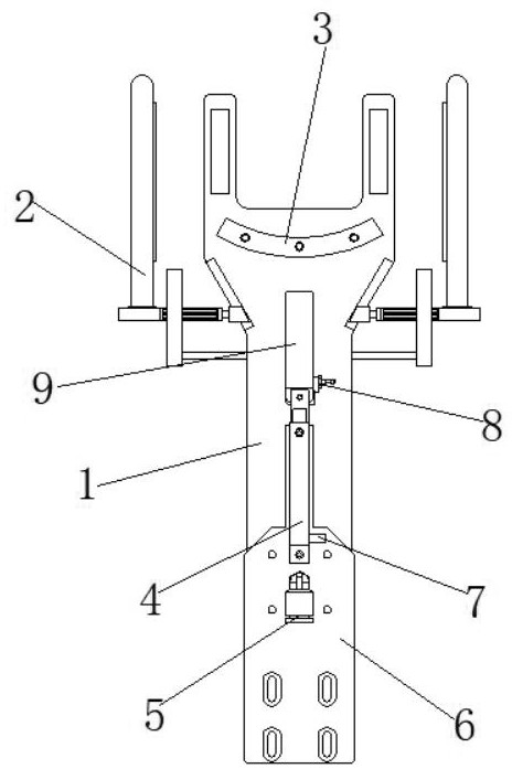
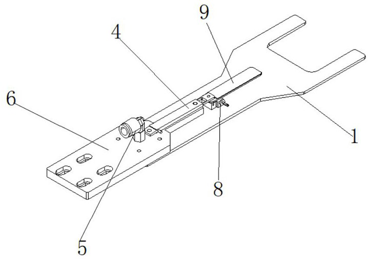
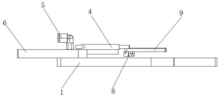
[0044] Example 2, as figure 1 , figure 2 , image 3 and Figure 9 As shown, when the wafer is placed on the manipulator base plate 1 at the same time, due to the serious warpage of the wafer surface and the multiple groups of vacuum suction heads 303 are far away from each other, at this time, the compressed air blowing plate 9 is driven by the micro cylinder 4 to the wafer. Move at the edge of the wafer, so that the compressed air port 903 moves to the edge of the wafer, and then the compressed air is delivered to the compressed air port 903 through the compressed air channel 904 through the compressed air line joint 8 through the blowing board, and the warpage Push the wafer to ensure that the wafer is attached to the manipulator base plate 1 to ensure reliable adsorption of the warped wafer. After completion, the micro cylinder 4 moves the compressed air blowing plate 9 to the original position to ensure that the compressed air blowing plate 9 for security.

[0045] Wo...


PUM


Abstract

The invention discloses a manipulator structure suitable for picking and placing warped wafers, including a manipulator base plate, an auxiliary arm is arranged at the front end of the top of the manipulator base plate, and a vacuum pipeline joint is arranged at the middle position of the top of the auxiliary arm. One end of the back of the auxiliary arm top is provided with a miniature cylinder, and one side of the miniature cylinder is provided with a compressed air pipeline connector for the miniature cylinder. In the present invention, multiple groups of vacuum adsorption heads are arranged on the arc-shaped vacuum adsorption chamber on the bottom plate of the manipulator. Under the action of the second spring, the vacuum adsorption heads are ejected, so that the telescopic length of the vacuum adsorption heads can be flexibly changed. It enables multiple sets of vacuum adsorption heads to be attached to the wafer surface with severe warping, ensuring that there is no air leakage between the vacuum adsorption heads and the severely warped wafer, and ensuring the vacuum stability of the vacuum adsorption robot base plate. Firmly absorb the wafer to prevent the wafer from falling due to shaking.

Description

technical field [0001] The invention relates to the technical field of electrical parameter testing and analysis of semiconductor discrete devices and GPP chips, in particular to a manipulator structure suitable for picking and placing warped wafers. Background technique [0002] With the increasing automation of equipment, fully automatic probe station equipment gradually replaces semi-automatic probe stations that require manual loading and unloading, and fully automatic probe stations have the advantages of high testing efficiency and low labor costs for operators; each manufacturer The thickness and processing technology of the wafers to be tested are different, resulting in different surface flatness of the wafers to be tested. The wafers with better flatness can be easily adsorbed on the pick-up robot. [0003] However, there are certain deficiencies in the existing manipulator structure: [0004] 1. For wafers with serious warping, due to the lack of vacuum ports and...

Claims


Application Information

Patent Timeline
Patent Type & Authority Patents(China)
IPC IPC(8): H01L21/683H01L21/687
CPCH01L21/6838H01L21/68707Y02P70/50
Inventor 段成龙邢莹胡晓霞周豪
Owner 三河建华高科有限责任公司
Why Eureka
Try Eureka