High-precision stable boring and milling machining center

A technology for boring and milling processing and machining centers, which is applied in metal processing equipment, metal processing mechanical parts, manufacturing tools, etc. It can solve the problems of high machining hole accuracy, loss, workpiece machining errors, etc., to ensure smooth operation and improve stability. , the effect of easy installation

Pending Publication Date: 2022-05-06
福建省龙治智能设备有限公司
View PDF0 Cites 0 Cited by
  • Summary
  • Abstract
  • Description
  • Claims
  • Application Information

AI Technical Summary

Problems solved by technology

[0002] The boring and milling machining center is a kind of equipment that can be used for boring and milling. The boring and milling machining center is generally a relatively large equipment, which is the same as the horizontal machining center. Because the centripetal force of the boring and milling machining center is relatively good, the ram can extend It is very long, and is generally used for processing box-type parts with high hole precision and relatively large volume. In order to facilitate the cutting of the workpiece, the workpiece mounting table will be rotated and controlled. The size of the workpiece is often larger than the X-axis movable seat at the lower end. When the installation position of the heavy and irregular workpiece is not in the center, and the installation table is in the process of rotation, it may have a certain inclination, so that the workpiece that requires high precision can be processed. error, causing trouble and loss

Method used


Image

  • High-precision stable boring and milling machining center
  • High-precision stable boring and milling machining center
  • High-precision stable boring and milling machining center

Examples


Embodiment Construction

[0030] The following will clearly and completely describe the technical solutions in the embodiments of the present invention with reference to the accompanying drawings in the embodiments of the present invention. Obviously, the described embodiments are only some, not all, embodiments of the present invention. Based on the embodiments of the present invention, all other embodiments obtained by persons of ordinary skill in the art without making creative efforts belong to the protection scope of the present invention.

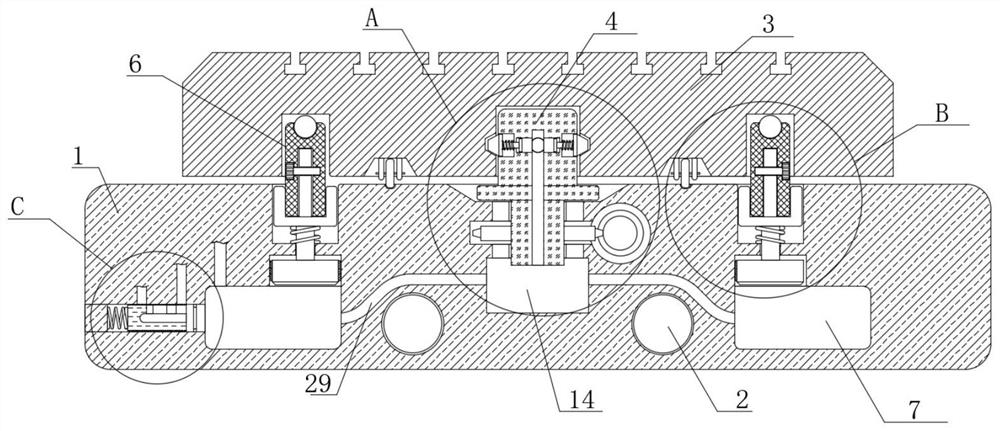
[0031] see Figure 1-8 , the present invention provides a high-precision and stable boring and milling machining center: the machining center includes:

[0032] The movable seat 1 is set on one side of the machining center through two X-axis screw screws 2;

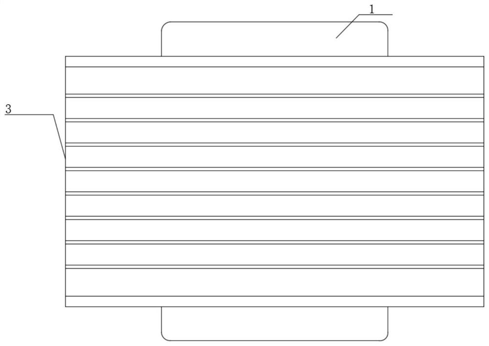
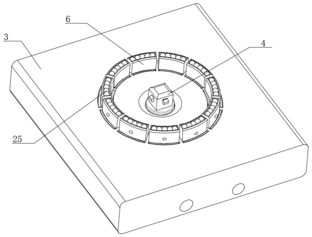
[0033] Mounting table 3, mounting table 3 is horizontally arranged on the upper end of the center of movable seat 1 through the connecting assembly, and the connecting assembly includes connecting seat 4...


PUM


Abstract

The invention relates to the technical field of machining machinery, in particular to a high-precision stable boring and milling machining center which comprises a movable seat, a mounting table, a control assembly, a supporting assembly, a high-pressure cavity and a stabilizing assembly, and a connecting seat and a plurality of supporting plates are arranged between the movable seat and the mounting table; supporting plates are used for auxiliary supporting, the stability of the mounting table is improved, when the mounting table inclines, the supporting plate on one side is extruded to damage high-pressure balance in a pressurizing cavity, and therefore communication between a reinforcing groove and the high-pressure cavity is opened under the action of an adjusting plug, air pressure in the high-pressure cavity is enhanced and improved, and stable operation of the mounting table is guaranteed; and in addition, under the action of an air supplementing groove, automatic air supplementing can be conducted on the high-pressure cavity, the set supporting stability strength and the high-pressure effect of the high-pressure cavity are kept all the time, connection between the connecting base and the mounting table is reinforced and fixed through the connecting block, and mounting is convenient.

Description

technical field [0001] The invention relates to the technical field of processing machinery, in particular to a high-precision and stable boring and milling machining center. Background technique [0002] The boring and milling machining center is a kind of equipment that can be used for boring and milling. The boring and milling machining center is generally a relatively large equipment, which is the same as the horizontal machining center. Because the centripetal force of the boring and milling machining center is relatively good, the ram can extend It is very long, and is generally used for processing box-type parts with high hole precision and relatively large volume. In order to facilitate the cutting of the workpiece, the workpiece mounting table will be rotated and controlled. The size of the workpiece is often larger than the X-axis movable seat at the lower end. When the installation position of the heavy and irregular workpiece is not in the center, and the install...

Claims


Application Information

Patent Timeline
IPC IPC(8): B23Q1/26
CPCB23Q1/262Y02P70/10
Inventor 陈天祥傅健健廖玲郑文挺蒋凤鸣
Owner 福建省龙治智能设备有限公司
Why Eureka
Try Eureka