
Pressing device of section steel stack packing line

A compression device and packaging line technology, applied in packaging, transportation and packaging, packaging/bundling items, etc., can solve problems such as dangerous accidents, increase the compression of mechanical devices, large height drop, etc. The effect of tightness

Pending Publication Date: 2022-05-06
SHANGHAI SHENTAI INTELLIGENT EQUIP
View PDF0 Cites 0 Cited by
  • Summary
  • Abstract
  • Description
  • Claims
  • Application Information

AI Technical Summary

Problems solved by technology

[0003] Due to the special structure of steel stacks: most of the outer contour surfaces are irregular planes or curved surfaces and the height difference between adjacent surfaces is large, so that the packing line cannot completely contact and hold tightly with all the outer contour surfaces of the steel stacks, and some steel wires and steel stacks The concave position is in a suspended state, so there is a hidden danger of loosening, which may easily cause loose packages during loading, transportation and unloading, resulting in dangerous accidents
At present, it is only possible to manually compress the packaged steel wire in the suspended position, and the effect is not good. Therefore, it is imperative to increase the compression of mechanical devices.

Method used


Image

  • Pressing device of section steel stack packing line
  • Pressing device of section steel stack packing line
  • Pressing device of section steel stack packing line

Examples


Embodiment 1

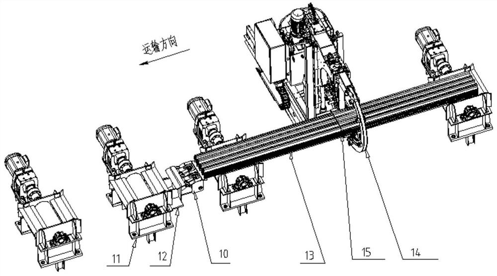
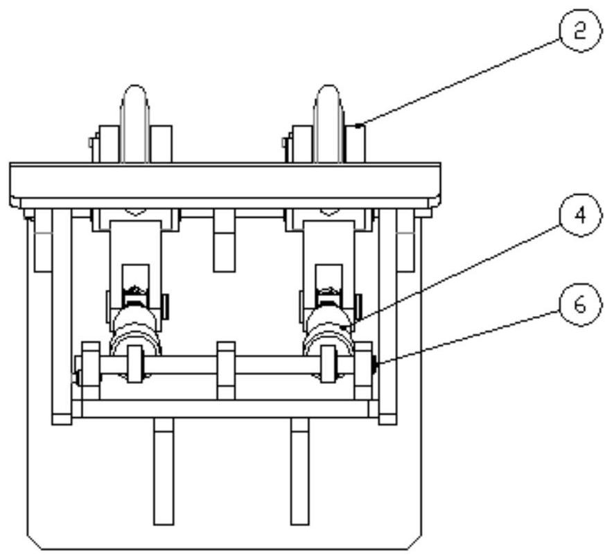
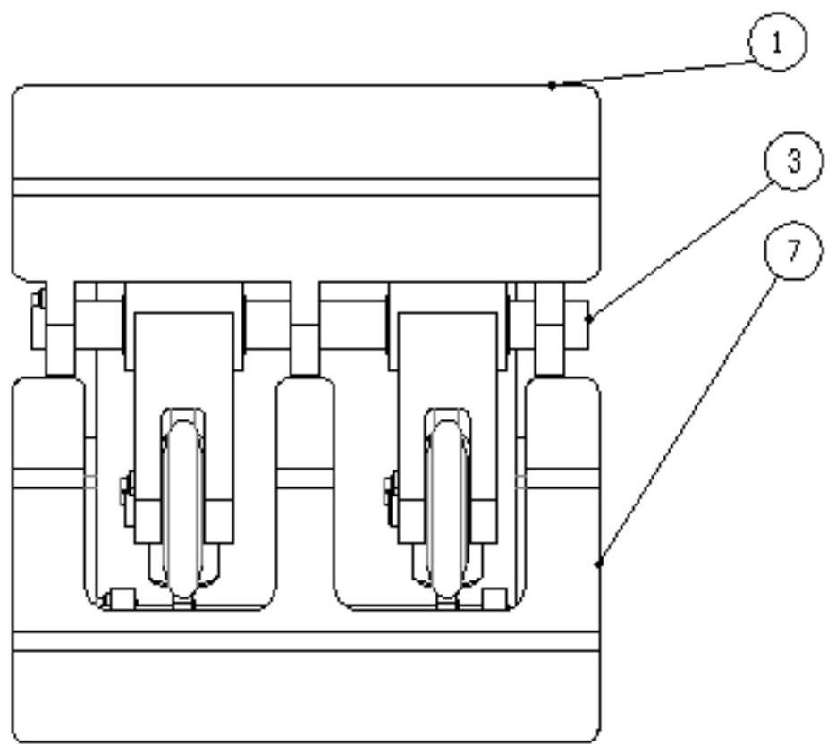
[0026] From figure 1 , figure 2 , image 3 , Figure 4 , Figure 5 It can be seen that the compression device of the profile steel stack packing line of the present invention includes a main bracket 1, a swing arm assembly 2, a main shaft 3, a spring rod assembly 4, a small shaft 6, and a guide plate 7; the main bracket 1 and the guide plate 7 are connected to form The outer frame; the swing arm assembly 2 is connected with the main support 1 through the main shaft 3, the spring rod assembly 4 is connected with the guide plate 7 through the small shaft 6; the spring rod assembly 4 is connected with the swing arm assembly 2.

[0027] When the profiled steel pile is transported through the conveyor line after being packaged, the swing arm assembly 2 will rotate and swing downward around the axis of the main shaft 3 under the action of its own weight, driving the spring rod assembly 4 to move, and then the spring in the spring rod assembly 4 The elastic force of the packing ...

Embodiment 2

[0030] From figure 1 , figure 2 , image 3 , Figure 4 , Figure 5 It can be seen that the compression device of the profile steel stack packing line of the present invention: the compression device also includes two upper and lower limit units, the two limit units are located on the same side of the main bracket 1, each limit unit includes a fixed plate I8, fixed Plate I8 is fixed on the outermost side of the upper connection hole or the lower connection hole of the main bracket 1 through fasteners, and one side of it is stuck in the groove at the outer circle of one end of the main shaft 3 or the small shaft 6 .

[0031] Wherein, the groove at the outer circle of the main shaft 3 or the small shaft 6 is a straight side, which is in contact with the side of the fixing plate I8.

[0032] The two fixing plates I8 respectively press the main shaft 3 and the small shaft 6 to restrain the rotation and axial movement of the two shafts, so that the swing arm assembly 2 set on t...

Embodiment 3

[0035] From figure 1 , figure 2 , image 3 , Figure 4 , Figure 5 , Figure 6 It can be seen that the compression device of the profile steel stack packing line of the present invention: the swing arm assembly 2 includes at least two groups of swing arm units arranged symmetrically from left to right, and each group of swing arm units includes a swing arm bracket 2-1, a roller 2-2, a connecting Axis 2-5, roller shaft 2-6; the roller 2-2 is located between the left and right forearms of the upper arm of the swing arm support 2-1, and the roller shaft 2-6 passes through the left and right forearms of the upper arm of the swing arm support 2-1, Roller 2-2 and cooperate with the inner holes of the three; connecting shaft 2-5 passes through the left and right small arms of the lower arm of swing arm bracket 2-1 and cooperates with the inner holes of both; connecting shaft 2-5 and spring rod assembly 4 connection; the main shaft 3 passes through the upper connecting hole of t...


PUM


Abstract

The invention discloses a pressing device of a section steel stack packing line. The pressing device comprises a main support, a swing arm assembly, a main shaft, a spring rod assembly, a small shaft and a guide plate. The main bracket is connected with the guide plate to form an outer frame; the swing arm assembly is connected with the main support through a main shaft. The spring rod assembly is connected with the guide plate through a small shaft. The spring rod assembly is connected with the swing arm assembly. The swing arm assembly comprises at least two sets of swing arm units, and each set of swing arm unit comprises a swing arm support, a rolling wheel, a connecting shaft and a rolling wheel shaft. The roller shaft penetrates through the left small arm and the right small arm of the upper arm of the swing arm support and the roller and is matched with inner holes of the left small arm, the right small arm and the roller; a connecting shaft penetrates through left and right small arms of the lower arm of the swing arm bracket and is matched with inner holes of the two small arms; the connecting shaft is connected with the spring rod assembly; the main shaft penetrates through an upper connecting hole of the main support and a middle hole of the swing arm support to be connected with the main support. According to the device, a packing line in a suspended position on a section steel stack can be compressed, so that dangerous accidents are avoided.

Description

technical field [0001] The invention relates to the field of iron and steel equipment, in particular to a compacting device for a profile steel stack packing line. Background technique [0002] In order to facilitate the transportation of the section steel produced on the section steel rolling production line, the section steel pile needs to be packed by a baler, and the packing line passes through the wire delivery device of the baler and winds the steel pile for a complete circle through the wire channel, and then takes up the wire, knots, and cuts the steel. Packing of stacks. [0003] Due to the special structure of steel stacks: most of the outer contour surfaces are irregular planes or curved surfaces and the height difference between adjacent surfaces is large, so that the packing line cannot completely contact and hold tightly with all the outer contour surfaces of the steel stacks, and some steel wires and steel stacks The concave position is in a suspended state, ...

Claims


Application Information

Patent Timeline
IPC IPC(8): B65B13/04B65B13/20B65B13/18B65B27/00
CPCB65B13/04B65B13/20B65B13/185B65B13/18B65B27/00
Inventor 刘剑锋杜刚伟刘晓佟袁茂华方浩龙平王新乐
Owner SHANGHAI SHENTAI INTELLIGENT EQUIP
Learn More