A mechanical transmission feeding device

A feeding device and mechanical transmission technology, which is applied to conveyors, conveyor objects, transportation and packaging, etc., can solve the problems of increasing production line costs, large space for feeding equipment, and large worktables, so as to save resources, improve efficiency, reduce The effect of rise and fall times

Active Publication Date: 2022-07-15
HEBEI CHEM & PHARMA COLLEGE
View PDF9 Cites 0 Cited by
  • Summary
  • Abstract
  • Description
  • Claims
  • Application Information

AI Technical Summary

Problems solved by technology

The disadvantage is that it takes up too much space for the feeding equipment. If large materials are transported, it is not conducive to the arrangement of the feeding equipment. Such an arrangement will eventually lead to a too large work surface, which will bring inconvenience to the processing and increase the cost of the production line.

Method used


Image

  • A mechanical transmission feeding device
  • A mechanical transmission feeding device
  • A mechanical transmission feeding device

Examples


Embodiment Construction

[0054] The present invention will be described in further detail below in conjunction with the accompanying drawings.

[0055] It should be explained that the terms "height", "width", "upper", "lower", "left", "right", etc. indicate the orientation or positional relationship based on the orientation or positional relationship shown in the drawings of the present application, only It is for convenience and simplicity of description, rather than indicating or implying that the device or element referred to must have a particular orientation, be constructed and operate in a particular orientation, and therefore should not be construed as an illustration of the present invention.

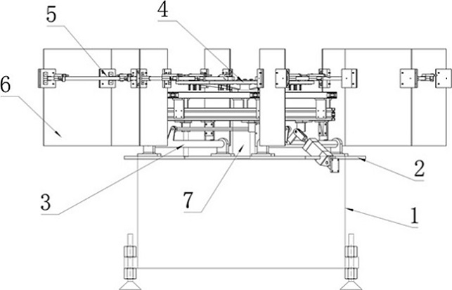
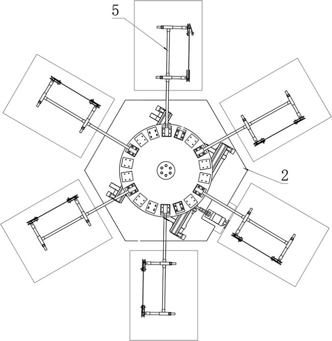
[0056] like Figure 1-8 As shown, a mechanical transmission feeding device includes a base 1, an adapter plate 2 fixedly connected to the upper end of the base 1, a lifting device 3 fixed on the adapter plate 2, and a lifting device 3 arranged on the lifting device 3. The rotating plate 4 at the upper en...


PUM


Abstract

The invention discloses a mechanical transmission feeding device, comprising a base, an adapter plate fixedly connected to the upper end of the base, a lifting device fixedly arranged on the adapter plate, a rotating plate arranged on the upper end of the lifting device, a feeding device arranged on the rotating plate and the sheets clamped on the feeding device are evenly distributed around the circumference; a rotating motor is fixedly connected to the lower end of the rotating plate; the rotating motor is fixedly arranged on the upper end of the lifting device; The rotating plate, the feeding device and the sheet material move up and down with the lifting device. The purpose of this application is to provide a transmission and feeding device for multi-directional transmission of sheet materials. The application is suitable for continuous feeding production lines. The rotary continuous conveying of sheet materials is used to provide a high-quality material for the subsequent processing of multiple automatic production lines of sheet materials. material work.

Description

technical field [0001] The invention relates to the field of automatic sheet material conveying machinery, in particular to a mechanical transmission feeding device. Background technique [0002] In the sheet material automation equipment, the conveying mechanism is widely involved in the integration. Most of the existing sheet material feeding devices use a single station, that is, the sheet material is taken out from the silo, grabbed by the manipulator and fed into the feeding device and sent to the next station. For processing, or directly transported to the feeding device, the feeding device adopts the method of belt drive and roller drive to convey the incoming materials. If multiple production lines are used, it is necessary to set the waiting interval to wait for the feeding device; the existing technology also uses one production line to use The arrangement of a feeding device increases the cost of the machine and occupies a large area, which is not conducive to the...

Claims


Application Information

Patent Timeline
Patent Type & Authority Patents(China)
IPC IPC(8): B65G47/90B65G47/84
CPCB65G47/902B65G47/847B65G2201/022
Inventor 马少丽
Owner HEBEI CHEM & PHARMA COLLEGE
Why Eureka
Try Eureka