Voltage controlled oscillator for loop circuit

A technology of voltage-controlled oscillator and loop, which is applied in the direction of automatic power control, electric pulse generator circuit, and logic circuit to generate pulses, etc. It can solve the problems of small input range, sensitive power supply noise, and poor phase noise, and achieve output The effect of large linear range, short rise and fall time, and low phase noise

Inactive Publication Date: 2012-06-06
SAMSUNG ELECTRONICS CO LTD +1
View PDF0 Cites 0 Cited by
  • Summary
  • Abstract
  • Description
  • Claims
  • Application Information

AI Technical Summary

Problems solved by technology

When Vctrl is close to the power supply voltage, affected by the channel length modulation effect of the MOS tube, the current mirror circuit exhibits nonlinear characteristics, so Vctrl is also limited in the high-voltage region
Therefore the input range of this circuit is small
[0010] 2. Poor adjustment linearity
Therefore, the regulation linearity of the circuit is poor
[0012] 3. Low power supply voltage sensitivity
The above-mentioned basic circuit is a single-ended oscillator, which is very sensitive to power supply noise, which leads to large output jitter and poor phase noise.
[0014] CMOS ring oscillators are widely used in loop VCOs due to their advantages of easy integration, large adjustment range, small layout area, and low power consumption, but poor noise performance has always been a drawback

Method used


Image

  • Voltage controlled oscillator for loop circuit
  • Voltage controlled oscillator for loop circuit
  • Voltage controlled oscillator for loop circuit

Examples


Embodiment Construction

[0030] Embodiments of the present invention will now be described in detail, examples of which are illustrated in the accompanying drawings, wherein like reference numerals refer to like parts throughout. The embodiments are described below in order to explain the present invention by referring to the figures.

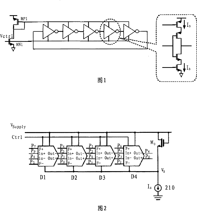
[0031] figure 2 The structure of a loop VCO 200 with even-numbered delay units according to an exemplary embodiment of the present invention is shown.

[0032] refer to figure 2 , the loop VCO 200 according to an exemplary embodiment of the present invention includes: a four-stage loop formed by delay units D1, D2, D3 and D4 and a bias circuit 210, wherein the delay units D1, D2, D3 and D4 have same structure. Ctrl is the input control voltage terminal of the loop VCO 200, which provides an input control voltage for controlling the delay of the loop VCO 200, and is connected to each control voltage input terminal of the delay units D1, D2, D3 and D4. Vsupply is t...


PUM


Abstract

The invention provides a loop circuit voltage control oscillator which comprises a time-delay unit in an even-number stage, wherein the same-phase input and the reverse-phase input of a common time-delay path in a time-delay unit in a first stage of the time-delay unit in an even-number stage are respectively connected with the same-phase input and the reverse-phase output of a time-delay unit ina previous stage of the time-delay unit of a first stage. The same-phase input and the reverse-phase output of the common time-delay path in a time-delay unit in every other stage are respectively connected with the reverse-phase output and the same-phase input of the time-delay unit in a pervious stage of the time-delay unit in every other stage. The input of a negative time-delay path of the time-delay unit in every stage of the time-delay unit in an even-number stage is connected with the output of time-delay units of the first two stages of the time-delay unit in every stage. The control-voltage input end and the power supply input end of the time-delay unit in every stage in the time-delay unit in an even-number stage are respectively connected with the input control voltage end of aloop circuit VCO and a DC power supply.

Description

technical field [0001] The present invention relates to a loop voltage controlled oscillator (VCO), and more particularly, to a loop VCO with low phase noise and improved output linear range. Background technique [0002] At present, PLL has a very wide application in SOC, such as clock recovery (clock recovery), frequency synthesis (frequency synthesis) and so on. As the core module of PLL, VCO also has higher and higher requirements in application. [0003] figure 1 is a diagram showing the circuit of a conventional basic loop VCO. [0004] refer to figure 1 , the traditional basic loop VCO circuit includes: a current mirror formed by transistors MP1 and MN1 and an odd-numbered loop formed by 5-level current-controlled inverters. Each stage of the current-controlled inverter is composed of a P-type transistor and an N-type transistor. [0005] Vctrl is the control voltage of the loop VCO, the current of MN1 and MP1 is adjusted through Vctrl, and the load capacitance i...

Claims


Application Information

Patent Timeline
Patent Type & Authority Patents(China)
IPC IPC(8): H03L7/099H03L7/08H03K3/027H03K5/13H03K5/134
Inventor 许幸
Owner SAMSUNG ELECTRONICS CO LTD
Why Eureka
Try Eureka