Visual detection device for leakage of cylinder cover
A detection device, cylinder head technology, applied in the direction of measuring device, by detecting the appearance of fluid at the leakage point, using liquid/vacuum degree for liquid tightness measurement, etc., can solve the cumbersome process, unable to judge the degree of leakage of the cylinder head, Problems such as high cost, to achieve the effect of easy leakage
- Summary
- Abstract
- Description
- Claims
- Application Information
AI Technical Summary
Problems solved by technology
Method used
Image
Examples
Embodiment 1
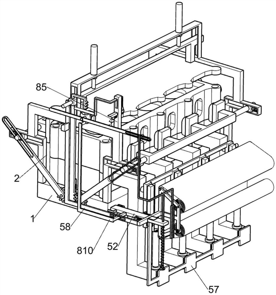
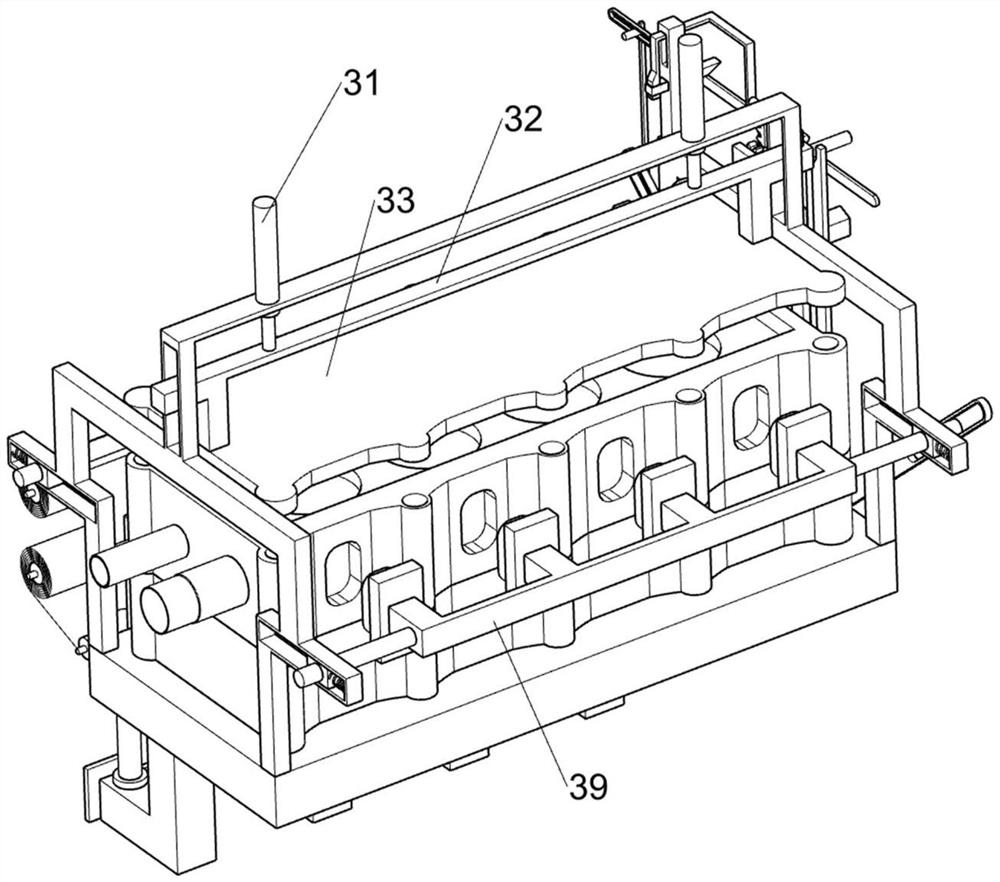
[0034] Cylinder head leakage detection device, such as figure 1 , figure 2 , image 3 , Figure 4 , Figure 5 , Figure 6 , Figure 7 , Figure 8 , Figure 9 and Figure 10 As shown, it includes a bottom support plate 1, a guide support frame 2, a cylinder head sealing limit part 3, a cylinder head leakage detection part 4 and an air guide frame shielding part 5. The top surface of the bottom support plate 1 is fixedly installed with a guide support Frame 2, the cylinder head airtight limit part 3 is set on the guide support frame 2, the cylinder head airtight limit part 3 is used to seal the top and both sides of the cylinder head, and the top surface of the bottom support plate 1 is fixedly installed with the cylinder head leakage Degree detection part 4, cylinder head leakage degree detection part 4 is used to detect the air tightness of the cylinder head, and the front side of the bottom support plate 1 is provided with an air guide frame shielding part 5.
[003...
Embodiment 2
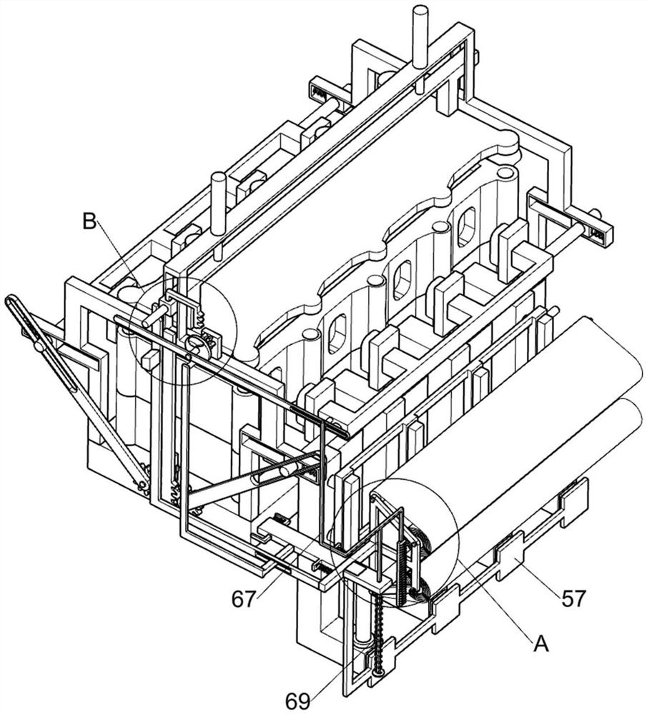
[0042] On the basis of Example 1, such as Figure 9 As shown, it also includes a cylinder head leakage degree recording part 6, which is rotatably connected to the movable frame 54, and the cylinder head leakage degree recording part 6 is used to record the cylinder head leakage degree data, The cylinder head leakage degree recording part 6 includes a guide roller 61, a winding roller 62, a paper delivery roller 63, a recording roll body 64, an overrunning clutch 65, a driven gear 66, a multi-position connecting rod 67, and a rack plate 68 and compression spring two 69, two guide rollers 61 are rotatably connected on the movable frame 54, and the winding roller 62 is rotatably connected to the movable frame 54, and the delivery roll 63 is also rotatably connected to the movable frame 54, and the paper delivery The recording roll body 64 is wound around the roller 63 and the unwinding roll 62. The take-up roll 63 is used to wind the recording roll body 64. Both guide rollers 61...
Embodiment 3
[0048] On the basis of Example 2, such as Figure 9 and Figure 11As shown, the recording roll paper position adjustment part 8 is also included, the recording roll paper position adjustment part 8 is fixedly installed on the guide support frame 2, the recording roll paper position adjustment part 8 is used to move the position of the recording roll paper body 64, The recording roll paper position adjustment part 8 includes an overrunning clutch two 81, a driven gear two 82, a cam plate 83, a pressing rack 84, a guide column 85, an inclined-plane pole 86, a connecting spring one 87, a belt inclined-plane adjustment frame 88 and Connecting spring 2 89, overrunning clutch 2 81 is fixedly installed on the support rod 72, driven gear 2 82 is fixedly connected on the overrunning clutch 2 81, cam disc 83 is fixedly connected on the support rod 72, connecting plate 32 top surface is fixedly connected with Press down the tooth bar 84, and the guide support frame 2 is fixedly installe...
PUM
 Abstract
Description
Claims
Application Information
 - R&D
- Intellectual Property
- Life Sciences
- Materials
- Tech Scout
- Unparalleled Data Quality
- Higher Quality Content
- 60% Fewer Hallucinations
Browse by: Latest US Patents, China's latest patents, Technical Efficacy Thesaurus, Application Domain, Technology Topic, Popular Technical Reports.
© 2025 PatSnap. All rights reserved.Legal|Privacy policy|Modern Slavery Act Transparency Statement|Sitemap|About US| Contact US: help@patsnap.com


